Microvascular Decompression for Hemifacial Spasm
This is a preview. Check to see if you have access to the full video. Check access
Microvascular decompression surgery for hemifacial spasm: Classic intraoperative findings
Please note the relevant information for patients suffering from hemifacial spasm is presented in another chapter. Please click here for patient-related content.
Hemifacial spasm (HFS) is a cranial nerve hyperactivity disorder most likely caused by neurovascular conflict (compression) as one of its underlying etiological phenomenon. It is typically characterized by unilateral involuntary intermittent twitching of the muscles of the face. The spasms usually start around the eye, involving the orbicularis oculi muscle, and later spread to other muscles of the face that are innervated by the facial nerve, including the platysma. The spasms are bilateral in about 2% of the patients with this disorder.
Hemifacial spasm has an estimated prevalence of 11 cases per 100000 individuals and is twice as common in females as males. Onset is mostly during the 4th and 5th decades of life. On average, patients suffer from HFS for about 8 years before definitive treatment is found. Familial clustering is rare.
Clinically, HFS presents as progressive, involuntary, irregular clonic or tonic movements of the muscles innervated by the facial nerve. The symptoms usually persist during sleep. Some patients complain of a “ticking” sound on the affected side, which is caused by contractions of the stapedius muscle.
Although HFS is not life threatening, patients may suffer severe psychological stress because of cosmetic concerns, and their binocular vision may be compromised by prolonged tonic spasms of the orbicularis oculi. The symptoms are often exacerbated by psychological stress and speaking.
Differentiating HFS from other movement disorders involving the face can sometimes be challenging. Some common mimickers of HFS are blepharospasm, facial nerve tics, and synkinesis after facial nerve paralysis. A careful history and physical examination can greatly help the clinician reach the correct diagnosis.
In most patients with HFS, the underlying cause is usually a neurovascular conflict caused by an ectatic or aberrant vessel loop of the posterior inferior cerebellar artery (PICA), the anterior inferior cerebellar artery (AICA), or the vertebral artery (VA), causing compression at the root exit zone of the facial nerve near the brainstem. The root exit zone is particularly sensitive to compression because the nerve is covered only by arachnoid in this location and epineurium is absent. Also, no connective tissue septa traverse the individual fascicles in this region that is the transition zone between central and peripheral myelin.
Two theories have been proposed to explain the pathogenesis of HFS. According to the peripheral hypothesis, ephaptic excitations occur at the root exit zone altered by the offending vascular loop. In contrast, the central hypothesis assumes that hyperexcitability of the facial motor nucleus within the brainstem is the underlying cause. I believe a combination of these two hypotheses most likely accounts for the pathogenesis of HFS. Vascular compression is a contributory and not necessarily the primary cause of this disorder.
Figure 1: One of Cushing’s patients (Circa 1920). Cushing is triggering the spasms by pinching the right side of the patient’s face.
Diagnosis and Evaluation
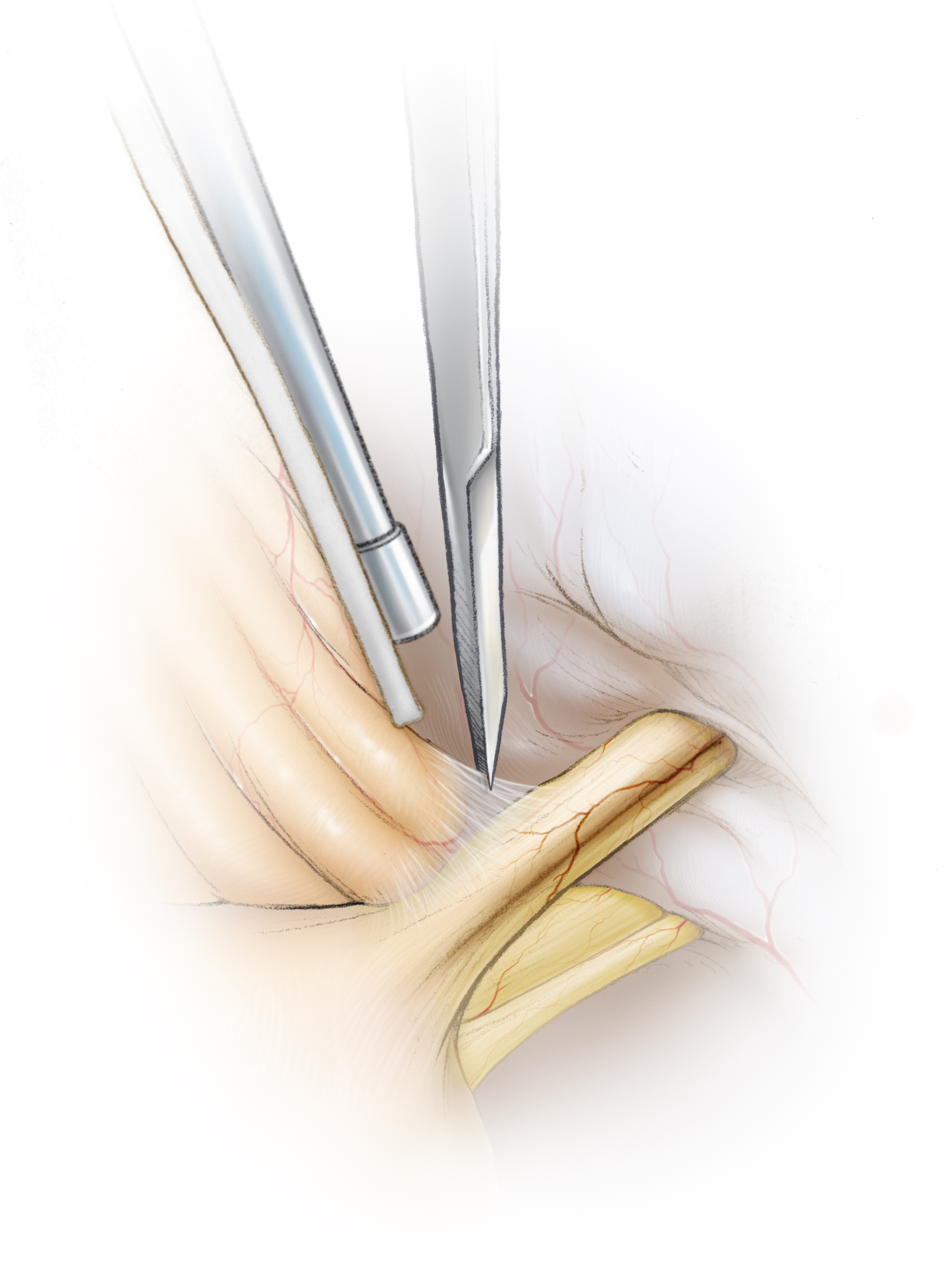
The clinical features at presentation are crucial for making the correct diagnosis of HFS. No imaging or testing modality has been found to reliably reach the diagnosis. Patients usually present with a fairly long history of involuntary spasms of the facial muscles innervated by CN VII, mostly originating in the periorbital region, involving the orbicularis oculi, and spreading to other facial muscles as the disease progresses.
They may complain of a “ticking” sound on the symptomatic side caused by stapedius muscle contractions. Patients are generally concerned about cosmesis, and some are significantly burdened by visual impairment (caused by prolonged tonic spasms of the orbicularis oculi) hindering their abilities to read and drive.
A detailed history and physical examination are important to reach the correct diagnosis. The patient should be asked about the onset of spasms, location, progression, exacerbating and relieving factors, and previous chemodenervating treatments with botulinum toxin injections. The patient should also be asked about a recent occurrence of Bell’s palsy because postparalytic facial synkinesis is an alternative diagnosis, although rare.
It is not unusual to find mild facial weakness caused by prior botulinum toxin injections, facial neuropathy related to vascular conflict, or facial muscle weakness caused by ongoing repetitive spasms. Any additional findings on exam, such as hearing loss, should raise concerns for an underlying structural lesion within the cerebellopontine angle such as schwannoma, meningioma, epidermoid tumor, or arachnoidal cyst. Certain disorders intrinsic to the brainstem, such as gliomas, multiple sclerosis, and brainstem stroke, can also give rise to similar symptoms and should be ruled out.
Some movement disorders that can mimic hemifacial spasm include blepharospasm (bilateral and synchronous symmetrical contractions of the eyelids), oromandibular dystonia (involuntary and sustained muscle spasms of the mouth and lower face), facial nerve tic (complex, coordinated, multifocal movement patterns, and switches between the right and the left sides of the face), hemimasticatory spasm, focal seizures, and synkinesis after facial nerve paralysis following acoustic neuroma surgery.
Before considering a microvascular decompression (MVD) procedure, the patient should undergo a CT scan or preferably a high-resolution dedicated posterior fossa MRI to rule out any structural pathology. The MRI will determine the extent of the tumor (epidermoid, meningioma, etc) and necessary preoperative considerations to resect the tumor. A high resolution T2–weighted sequence may display an aberrant vascular loop at the root exit zone of the nerve.
Even if a high-resolution MRI does not identify an offending vascular loop, I offer posterior fossa exploration to the patient if I am relatively certain of the diagnosis. The MR sequences can also evaluate the presence of a large tortuous vertebral artery that may not be safely or effectively mobilized intraoperatively. In this situation, the surgeon should discuss the lower rate of spasm freedom after surgery with the patient.
Figure 2: Axial T2-weighted MRI demonstrates a vascular loop (arrow) around the root exit zone of CN VII.
Figure 3: The only presentation of this large left-sided petroclival epidermoid tumor (note the CP angle extension around the facial nerve *) was hemifacial spasms. This tumor was resected through staged retrosigmoid and pterional craniotomies.
Medical Therapy
The drugs used to treat hemifacial spasm include carbamazepine, clonazepam, baclofen, and gabapentin, but success rates with these medications have been disappointing. The adverse effects of these medications notably affect some patients: fatigue, exhaustion, and poor performance. Botulinum toxin (Botox) targeted chemical denervation injections may help reduce spasms, but this is merely symptomatic treatment.
Since these injections do not treat the cause of the problem, spasms gradually return at the end of each 3 to 6-month Botox cycle, necessitating repeat treatment. Botox injections may also injure some of the motor nerve terminals and partially account for some residual facial weakness after MVD surgery, despite successful relief of spams.
Most importantly, the gradual return of spasms at the end of each Botox cycle often leads the patient to seek a more lasting definitive treatment. Microvascular decompression surgery has a reported lasting success rate of 80-90% in experienced hands and appropriately selected patients, and is the only durable therapeutic option.
Indications for Surgery
Most patients elect to proceed with surgery because of the disfiguring nature of HFS spasms and a desire for an improved cosmetic outcome. Although Botox injections can provide considerable albeit short-lasting relief, the need to undergo these injections every 3 to 6 months and the cosmetic deformity associated with HFS and Botox injections are the main reasons to consider MVD surgery.
Many surgeons prefer to see the patient in his or her “off” period to assess the validity of the spasms before offering surgery, but this has not been the routine in my practice. Patients suffering from HFS are generally reliable and know much about their disorder. They frequently have videotaped their spasms during their “off” period.
Since HFS is usually not a disabling disease, surgical intervention must be conducted with very minimal risk to justify the risk-to-benefit ratio. As with MVD for trigeminal neuralgia, the operator’s experience is especially important in achieving a favorable and safe outcome.
The patient’s history and severity of spasms are very important because spasms are sometimes self-limiting and resolve spontaneously. For this reason, I offer MVD surgery only if the patient has experienced severe HFS symptoms for longer than 1-2 years.
Contralateral hearing loss is also a contraindication to MVD surgery for HFS. Functional hearing loss is a real complication from this procedure (<5%) and should be candidly discussed with patients preoperatively.
Preoperative Considerations
I advocate using brainstem auditory evoked response (BAER) monitoring during MVD to treat HFS (in contrast with MVD for trigeminal neuralgia, when I do not use BAER monitoring). Latency of Peak V is considered the best electrophysiologic indicator for signaling cochlear nerve damage. I also look for intraoperative disappearance of lateral spread reflex (LSR), a measure of hyperactivity of the facial nerve/nucleus. This reflex is produced by electrical stimulation of the temporal or zygomatic branch of the facial nerve, which leads to a response recorded from the mentalis muscle.
The disappearance of LSR after surgery informs the surgeon that the appropriate pathology was adequately discovered and addressed. However, while the disappearance of LSR is reassuring, its persistence is not inconsistent with complete postoperative relief of spasms as long as a convincing offensive vascular loop was identified intraoperatively and handled appropriately.
Operative Anatomy
Click here to view the interactive module and related content for this image.
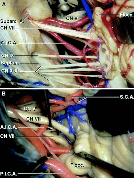
Figure 4: Exposure of the cranial nerves in the cerebellopontine angle after a right-sided retrosigmoid approach. Note the relationship of the AICA and PICA to the CN VII/VIII complex (A). The facial nerve is located anterior to the superior vestibular nerve. The AICA or its labyrinthine branch transecting the CN VII/VIII complex are often not the main offending vessels and must be carefully handled during surgery to avoid hearing loss (B)(Images courtesy of AL Rhoton, Jr).
Figure 5: An enlarged view of the left cerebellopontine angle and its contents when viewed from a retrosigmoid approach. Note the relationship of AICA to CN VIII (A). The subarcuate artery must be preserved during operative maneuvers. The vestibulocochlear nerve and flocculus have been elevated to expose the junction of the facial nerve at the brainstem (B).
It is important to remember that the retrosigmoid approach exposes the root exit zone of the facial nerve at the brainstem below the root entry zone of the vestibulocochlear nerve (Images courtesy of AL Rhoton, Jr).
MVD for HEMIFACIAL SPASM
I routinely use the infraflocculus route through a small retromastoid craniotomy to reach the root exit zone of the facial nerve. The general technical nuances for an extended retromastoid craniotomy are presented in the Cranial Approaches Volume. In the following section, I review the specific steps of exposure during MVD for HFS.
Figure 6: Modified reverse “U” skin incision whose summit is marked 1cm below the presumed junction of the transverse and sigmoid sinuses. Note the position of the head in the skull clamp.
Figure 7: The operative corridors and trajectories for accessing the cerebellopontine angle: The surgical corridors for microvascular decompression for trigeminal neuralgia (supralateral cerebellar approach-blue arrow) and hemifacial spasm, and glossopharyngeal neuralgia (infralateral cerebellar or infrafloccular approach-green arrow) are illustrated.
Mobilization of the cerebellum in a purely medial direction must be avoided since this vector of retraction will be parallel to the sensitive CN VIII, increasing the risk of hearing loss. I use the infralateral cerebellar corridor through the infraflocculus route to access the root exit zone of CN VII.
Figure 8: Burr hole and craniotomy (HS: hemifacial spasm, GN: glossopharyngeal neuralgia). A single burr hole is created at the edge of the sigmoid sinus and 1 centimeter below the transverse sinus. The size of the craniotomy or craniectomy is often small, about 1.0-1.5 times the size of a quarter coin.
A craniotomy should be avoided in older patients with adherent venous dural surface. The last osteotomy (2) is near the sigmoid sinus. The bone over the sigmoid sinus is removed during the next step using an air drill. For additional nuances, please refer to the extended retromastoid craniotomy chapter.
Figure 9: The method for dural opening (top image). A magnified operative photo also demonstrates the extent of craniotomy and dural opening (bottom image). There is no need to expose the transverse sinus. Unlike the linear skin incision, the curvilinear incision mobilizes the retracted myocutaneous flap inferiorly and prevents it from increasing the operator’s working distance.
INTRADURAL PROCEDURE
Figure 10: Supramedial cerebellar retraction: A piece of glove (cut slightly larger than the cottonoid patty) acts as a rubber dam. It protects the cerebellar hemisphere against the rough surface of the cottonoid as the rubber dam slides over the cerebellum while dissection is continued to expose the cerebellopontine angle (top image). I identify the junction of the petrous bone and the floor of posterior fossa (P, bottom intraoperative image) and advance the cottonoid over the rubber dam near the turn of the petrous bone toward the lower cranial nerves.
Medial retraction of the cerebellum parallel to CN VII/VIII is avoided to prevent direct transmission of retraction to these nerves. The vector of retraction is parallel to CN IX. Note that I do not apply fixed retractors, but instead use the suction apparatus to mobilize the cerebellar hemisphere in a dynamic fashion during dissection. Along with generous opening of the regional arachnoid membranes over the cranial nerves, this maneuver minimizes the risk of hearing loss. Dynamic retraction of the suction apparatus allows intermittent exposure only where needed. Aggressive retraction of fixed retractors often provides exposure at places that may not be necessary.
Figure 11: I sharply dissect the arachnoid membranes over the lower cranial nerves and identify CN IX. Supramedial cerebellar mobilization allows me to follow the path of this nerve to the exit zone of CN VII at the level of the brainstem. Intraoperative BAER monitoring guides the surgeon to adjust retraction to minimize undue traction on CN VIII.
I continue irrigating the field periodically during intradural dissection because the intense light of the microscope can cause heat injury to CN VIII. I also cover the surface of CN VIII with a small piece of papaverine-soaked gelfoam to relieve vasospasm. If the BAERs change at anytime during the intradual procedure, I perform the following steps:
- Stop dissection and relieve all retraction while irrigating the operative field.
- Allow a few minutes for the BAERs to return to normal. It may be necessary to increase the blood pressure. Before reapplying dynamic retraction, I further dissect the arachnoid membranes over CN VII/VIII to relieve any traction on these nerves while mobilizing the medial cerebellum. I also cover these nerves with a small piece of papaverine-soaked sponge to relieve any vasospasm caused by traction and the heat of the microscope.
- I then attempt more superiorly directed retraction and use the infrafloccular corridor while minimizing any traction parallel to the CN VII/VIII complex.
Figure 12: The arachnoid membranes over the CN VII/VIII complex are split sharply, close to the brainstem, to prevent undue traction on these nerves during mobilization of the flocculus.
Figure 13: Microscissors are used to sharply open the arachnoid layers between the CN VII/VIII complex and cerebellum/flocculus.
Figure 14: In rare circumstances, I coagulate and shrink a small portion of the cerebellar flocculus overlying the root exit zone of CN VII to facilitate exposure of the root exit zone while minimizing the required force of retraction.
Figure 15: Neurovascular conflict leads to gray discoloration of the root exit zone of CN VII. This root exit zone is anterior and slightly inferior to the root entry zone of CN VIII (more whitish in color) and may be directly seen upon gentle elevation of CN VIII using a fine dissector. The offending vessel (most commonly the posterior or anterior inferior cerebellar artery) is hidden in the axilla of CN VII and may be mobilized and padded away from the nerve with pieces of shredded Teflon.
The perforators originating from the compressing vessel should be protected during this mobilization. Note that the site of the neurovascular conflict is along the root exit zone of CN VII near the brainstem. This area must be thoroughly examined using the following techniques: Wide opening of the arachnoid membranes and strategic use of dynamic retraction using suction apparatus at the appropriate operative angles.
Figure 16: An intraoperative photo (top image) demonstrates the area of discoloration (black arrow) at the root exit zone of the left facial nerve caused by the adjacent vascular loop. The lower image shows the final result after mobilization of the offending artery and implantation of Teflon. Please note the piece of papaverine-soaked gelfoam (yellow arrow) covering CN VIII. This piece of gelfoam relieves vasospasm of intraneural vessels and protects the nerve from the intense heat of the microscope.
Figure 17: I believe that the offending vessel’s entire length along the root exit zone of CN VII and the area over the brainstem should be padded with Teflon. The lateral spread reflex, present in most patients, may disappear upon mobilization of the artery. Although this test is not an absolute, the disappearance of the reflex is reassuring that the pathologic entity has been found and managed appropriately.
I place the shredded Teflon implant piecemeal between the artery and brainstem. An intact (unshredded) Teflon patch may be easily dislodged postoperatively, so its use is discouraged. These pieces of prosthesis are pushed superiorly and inferiorly (inset) to mobilize the artery along its entire length and away from the brainstem.
Figure 18: The implant has mobilized the artery along its entire length away from the root exit zone and the brainstem. It is important to remember that the presumed site of neurovascular conflict is at the root exit zone of the nerve near the brainstem and not only along the nerve’s cisternal segment.
Inadequate exposure of the root exit zone is the primary reason for inadequate decompression. The offending vessel(s) may be hidden deep in the arachnoid membranes or at the depth of the cleft formed by the cerebellum and brainstem (cerebellopontine fissure).
The surgeon’s lack of experience or fear of excessive retraction (due to limited familiarity with the use of dynamic retraction) does not justify inadequate exposure of the deeply located CN VII root exit zone and ultimately inadequate arterial mobilization. More often than realized, the surgeon mistakenly mobilizes the vessel along the nerve instead of along its hard-to-reach root exit zone and brainstem, leading to suboptimal operative outcome.
Closure
Figure 19: The dura is approximated primarily. I do not persist on performing a watertight dural closure and have experienced a very low rate of cerebrospinal fluid leak through the incision or the nose. Mastoid air cells are rewaxed thoroughly (“wax in, wax out”) and the bone flap is replaced or a methyl methacrylate cranioplasty is performed. The muscle and scalp are closed in anatomic layers.
Repeat MVD for Hemifacial Spasm
Factors that contribute to the failure of the first surgery include restricted and inadequate retromastoid craniectomies that did not extend laterally to the level of the sigmoid sinus or inferiorly to the level of the posterior fossa floor.
In addition, although the cisternal portion of the facial nerve should be inspected to relieve any neurovascular conflict there, meticulous examination of the root exit zone near the brainstem is mandatory in every case. I have operated on a number of patients who underwent an unsuccessful attempt elsewhere and I have routinely found a convincing offending vessel near the facial nerve root exit zone. In these cases, the initial surgeon presumably only handled the conflict along the brainstem.
Repeat MVD for Hemifacial Spasm: Pitfalls
Postoperative Considerations
Patients are usually admitted to the neuro intensive care unit for overnight observation and then transferred to the regular ward for a couple of days before they can be discharged home. Special attention should be paid to hemodynamic parameters, the neurologic examination, and wound care. Steroids are administered to prevent aseptic meningitis and minimize postoperative nausea and headaches.
Delayed resolution of spasms is not uncommon, and patients should be assured of this if a convincing arterial loop was identified intraoperatively. We do not routinely perform a head CT scan postoperatively. Occasionally, delayed facial palsy may occur after MVD for HFS. This palsy is temporary and responds well to a dexamathasone taper of 1 week in duration.
Pearls and Pitfalls
- Hemifacial spasm is an uncommon cranial nerve hyperactivity disorder characterized by unilateral, involuntary, intermittent twitching of the facial muscles. Spasms typically start around the eye, involving the orbicularis oculi muscle, followed by involvement of other muscles of the face that are innervated by the facial nerve, including the platysma.
- Differential diagnosis of HFS, particularly postparalytic facial synkinesis, facial tics, and blepharospasm, should be kept in mind and ruled out with the aid of an extensive history and a detailed neurologic examination.
- The cerebellum should be retracted only parallel to the direction of CN IX to avoid direct traction on CN VIII. Sharp arachnoid dissection and strategic dynamic cerebellar retraction will facilitate cerebellar mobilization without placing the cranial nerves at risk. These maneuvers allow adequate exposure to permit safe mobilization of the offending vascular loop and Teflon implantation.
- While mobilizing the offending vessel, it is important that the vessel be moved away from the brainstem at the root exit zone and padded with shredded Teflon; failure to do so will lead to suboptimal results.
Contributor: Aqueel Pabaney, MD
References
Barker FG 2nd, Jannetta PJ, Bissonette DJ, Shields PT, Larkins MV, Jho HD. Microvascular decompression for hemifacial spasm. J Neurosurg. 1995;82:201-210.
Cohen-Gadol AA. Microvascular decompression surgery for trigeminal neuralgia and hemifacial spasm: Naunces of the technique based on experiences with 100 patients and review of the literature. Clin Neurol Neurosurg. 2011;113:844-853.
McLaughlin MR, Jannetta PJ, Clyde BL, Subach BR, Comey CH, Resnick DK. Microvascular decompression of cranial nerves: lessons learned after 4400 operations. J Neurosurg. 1999;90:1-8.
Polo G, Fischer C, Sindou MP, Marneffe V. Brainstem auditory evoked potential monitoring during microvascular decompression for hemifacial spasm: intraoperative brainstem auditory evoked potential changes and warning values to prevent hearing loss--prospective study in a consecutive series of 84 patients. Neurosurgery. 2004;54:97-104.
Rhoton AL Jr. The cerebellopontine angle and posterior fossa cranial nerves by the retrosigmoid approach. Neurosurgery. 2000;47:S93-129.
Rosenstengel C, Matthes M, Baldauf J, Fleck S, Schroeder H. Hemifacial spasm—conservative and surgical treatment options. Dtsch Arztebl Int. 2012;109: 667−673.
Sindou MP. Microvascular decompression for primary hemifacial spasm. Importance of intraoperative neurophysiological monitoring. Acta Neurochir (Wien). 2005;147:1019–1026.
Please login to post a comment.

