Retromastoid Craniotomy Free


This is a preview. Check to see if you have access to the full video. Check access
Retromastoid Craniotomy for Acoustic Tumor
General Considerations
As in the case with the pterional craniotomy for supratentorial parasellar lesions, the retromastoid craniotomy is the workhorse of infratentorial approaches for reaching the cerebellopontine (CP) angle and ventrolateral brainstem.
Based on the definition of the extended pterional approach, lateral sphenoid wing is resected to the level of the superior orbital fissure and the roof of the orbit is flattened to provide an unobstructed operative corridor toward the subfrontal and parasellar area. Similarly, I define the extended retromastoid approach as a modification of the standard retromastoid craniotomy that includes partial removal of the bone over the sigmoid sinus.
This “untethering” of the sigmoid sinus allows its lateral mobilization using retraction sutures after dural opening. This maneuver expands the lateral operative trajectory toward the CP angle while reducing the retraction on the cerebellar hemisphere.
This extended retromastoid craniotomy must be tailored to the specific target pathology. The following steps describe the general principles of this approach, whereas the individual chapters on specific lesions and disorders (ie cranial nerve compression syndromes) review tailored exposures via this route.
Atlas Choice Tapered Pattie Collection
Low-profile for maximal visualization and protection
Tapered shape designed for retractorless surgery
Unparalleled flexibility and non-stick features
Indications for the Approach
This approach is flexible, efficient and familiar to all neurosurgeons. This versatile and adaptable exposure can reach almost all lesions within the CP angle and ventrolateral brainstem with gentle retraction and mobilization of the forgiving lateral cerebellar hemisphere.
The different petrosectomy exposures to the ventrolateral and anterior brainstem are most likely overutilized as the extended retrosigmoid route offers many of the same advantages with minimal morbidity. Although the location and size of the tumors dictate the appropriate operative approach, the texture of the tumor-fibrous (meningioma), soft and suckable (epidermoid)-also plays a crucial role in selection of a more expanded pathway to the anterior brainstem. For example, a large epidermoid tumor crossing the ventral brainstem can be removed through the retrosigmoid approach while a similar fibrous ventralateral meningioma with vascular encasement may require petrosectomy.
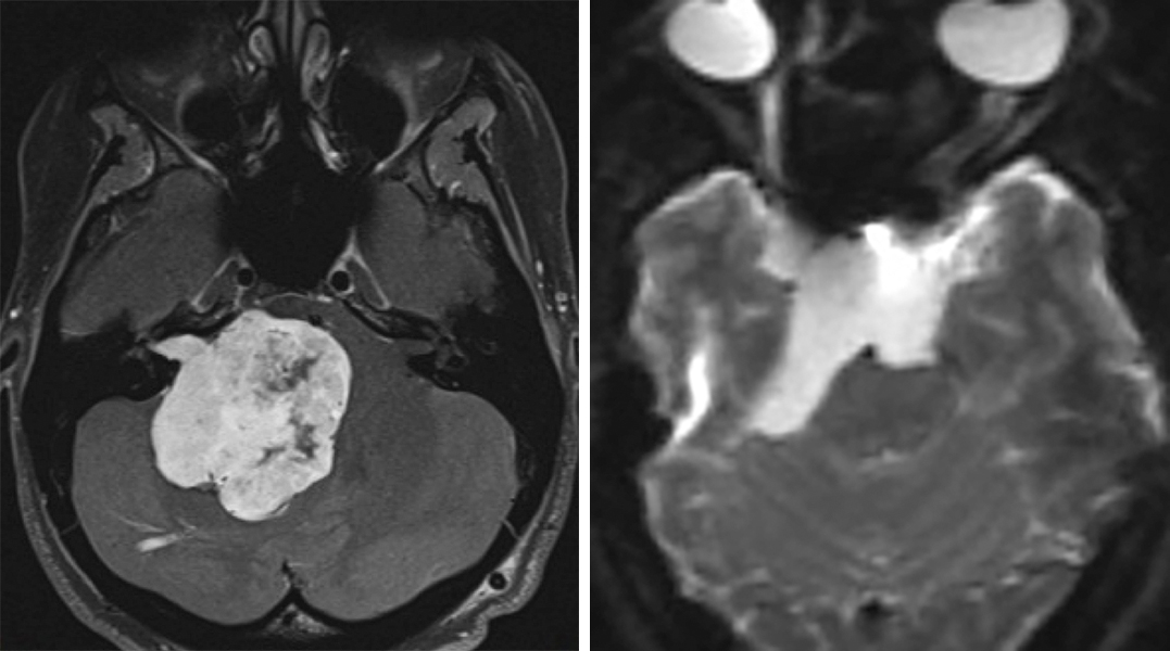
Figure 1: Giant acoustic tumors (left) and ventrally located epidermoids (right) can be removed though an expanded retrosigmoid approach.
In simple terms, the operative corridor for the extended retrosigmoid approach extends from the ventrolateral midbrain and upper clivus to the ventrolateral medulla and lower clivus.
Preoperative Considerations
Monitoring brainstem auditory evoked responses (BAERs) during microvascular decompression (MVD) for hemifacial spasm and other lesions that potentially require dynamic retraction parallel to and affecting the CN VII/VIII complex is recommended. Latency of peak V is considered the best electrophysiologic indicator for signaling cochlear nerve injury. Contralateral hearing loss may be a contraindication for retromastoid craniotomy.
The transverse and sigmoid venous sinuses may have a slightly variable location along the temporal and occipital bones. Patients with short necks or mild brachycephaly may also have a short sigmoid sinus and their transverse-sigmoid junction may be displaced inferiorly, disrepecting anatomical landmarks. These variations can be studied on preoperative scans and considered during craniotomy. These anatomical variations can easily disorient the surgeon and lead to venous sinus injury or restricted bony exposure leading to ineffective lesional access.
Generous mastoid air cells increase the risk of postoperative CSF fistula.
Operative Anatomy
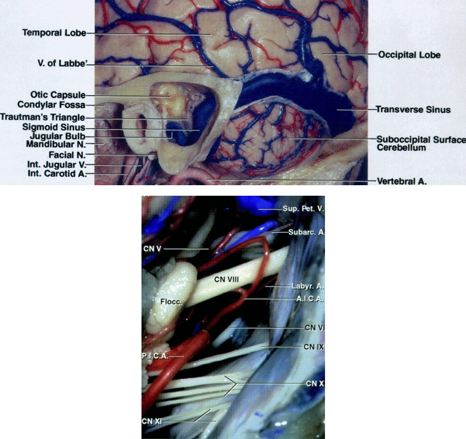
Figure 2: The transverse and venous sinuses and their relationships to bony anatomy including the mastoid tip and groove (top image). Exposure of cerebrovascular structures within the right cerebellopontine (CP) angle through the retromastoid approach in demonstrated (bottom image). Please note that the trigeminal nerve is “deeper” within the operative field and further away from the surgeon while the CN VII/VIII complex is more superficial and follows an oblique inferior to superior trajectory (Images courtesy of AL Rhoton, Jr).
RETROMASTOID CRANIOTOMY

Figure 3: The surgical technician who hands the instruments to the surgeon stands across from the surgeon. The surgeon either stands (during exposure and craniotomy) or sits (during intradural microsurgery). This position of the surgeon relative to the technician allows an easy transfer of surgical instruments between them.
The anesthesiologist may stand by the patient’s foot—this provides additional space for assistants and the rest of the operating team. I prefer to be sitting during microsurgery and position the patient with this preference in mind (lateral position for posterior fossa operations).

Figure 4: The patient is placed in the park-bench position with his or her head immobilized in a skull clamp. I perform a lumbar puncture before draping the incision in order to drain approximately 35-40cc of CSF and achieve posterior fossa decompression. This maneuver drops the intracranial tension and significantly facilitates the safety of opening the dura and “going around” the cerebellum to reach the CP angle cisterns during the early intradural dissection process.
Entry into the CP angle can be a challenging step during this approach and should be simplified by performing the lumbar puncture. The CSF is allowed to drain into a cup while I prepare and mark the incision on the suboccipital region.
The park-bench position prevents the non-physiologic neck posture that would occur if the patient were in a supine position. The supine position requires a significant turn in the patient’s neck, often leading to venous congestion. For these reasons, I believe the park-bench patient position decreases postoperative neck pain.
The patient’s ipsilateral shoulder is allowed to fall forward and is mobilized caudally away from the incision, therefore providing additional space within the surgical field. This maneuver is ergonomically important as it prevents a bulky shoulder, especially among obese patients with short necks, from obstructing the operative working space in the suboccipital area. Lack of attention to this detail can substantially limit operative movements.
The patient should be well secured to the operating room table to prevent risk of his or her displacement. To avoid risk of common peroneal nerve palsy, I do not place tape directly over the head of the fibula.

Figure 5: The position of the patient’s head in the skull clamp with the mastoid bone the highest point within the operative field is demonstrated. Note that the slight head rotation assists with expanding the operative corridor while the surgeon “goes around” the cerebellum to expose the CP angle. The pins of the skull clamp are situated outside the operator’s working zone.
The head of the patient is slightly flexed and turned toward the floor. The head of the bed may be flexed 15 degrees upward, and then the entire table is slightly angled in the Trendelenburg position to lower the patient’s head 10 degrees. The latter maneuver brings the operative area into a horizontal plane.
For tumors approaching the middle aspect of the clivus and displacing the brainstem, I do not rotate the head toward the floor so that the operative viewing angle toward the medial brainstem is not compromised by the overhanging lateral cerebellar hemisphere.
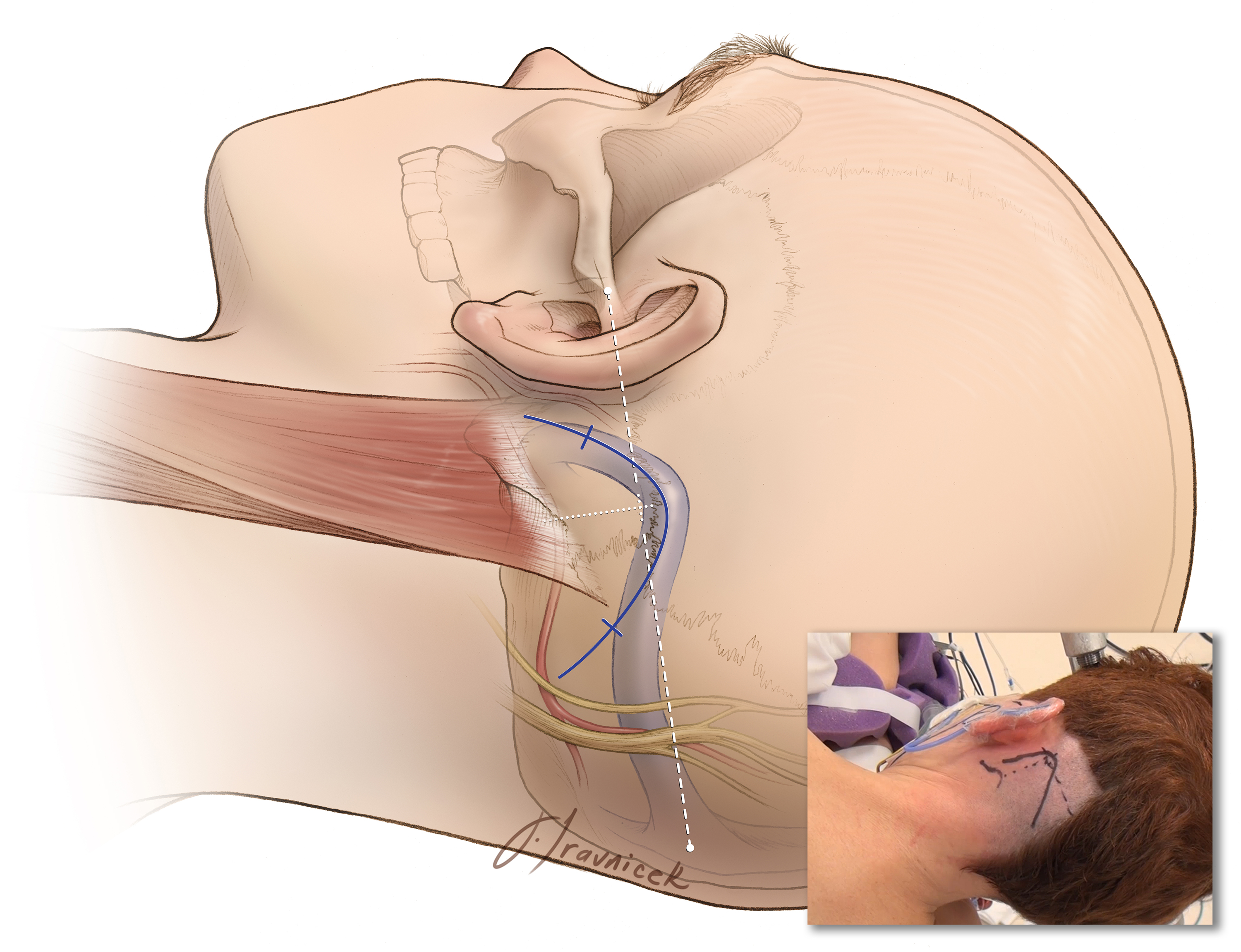
Figure 6: I use the modified reverse “U” skin incision whose summit is marked just below the presumed junction of the transverse and sigmoid sinuses. Please see the advantages of this incision listed below. The summit is marked where the transverse sinus (the horizontal hashed line in white connecting the inion to the root of zygoma) crosses the vertical hashed line in white, marking the mastoid groove. For large acoustic tumors, the base of the incision is widened so that a larger craniotomy can be accomplished.
I use the modified reverse "U" incision, originally described by Walter Dandy. This incision has certain advantages over the more commonly used variations of the linear incision.
The reverse "U" incision:
- Obviates the need for muscle dissection caudal to the posterior fossa floor and, in my experience, leads to less postoperative suboccipital pain.
- Reflects and mobilizes the myocutaneous scalp flap inferiorly, out of the surgeon’s working zone. The linear incision, in contrast, often accumulates the scalp and muscle layers under the scalp retractor and increases my working distance.

Figure 7: The curvilinear incision reflects and mobilizes the myocutaneous scalp flap inferiorly, out of the surgeon’s working zone (left image). The linear incision accumulates the scalp and muscle layers under the scalp self-retaining retractor and increases the operator’s working distance (right image)(with permission from IU Health).
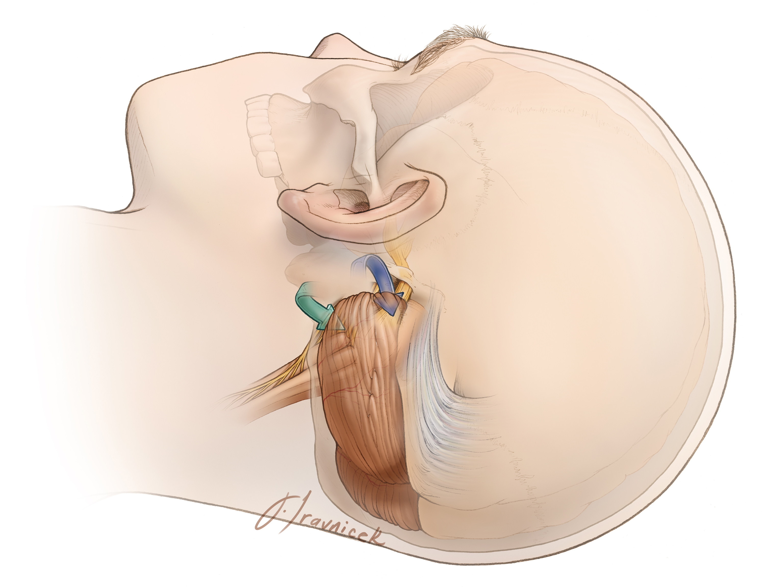
Figure 8: The operative corridors and trajectories for accessing the CP are illustrated. The surgical corridors for reaching lesions above the CN VII/VIII complex (supralateral cerebellar approach- blue arrow) and below the CN VII/VIII complex (infralateral cerebellar or infrafloccular approach-Green arrow) are illustrated. Mobilization of the cerebellum in a purely medial direction must be avoided since the vector of retraction will be parallel to the sensitive CN VIII, increasing the risk of hearing loss.
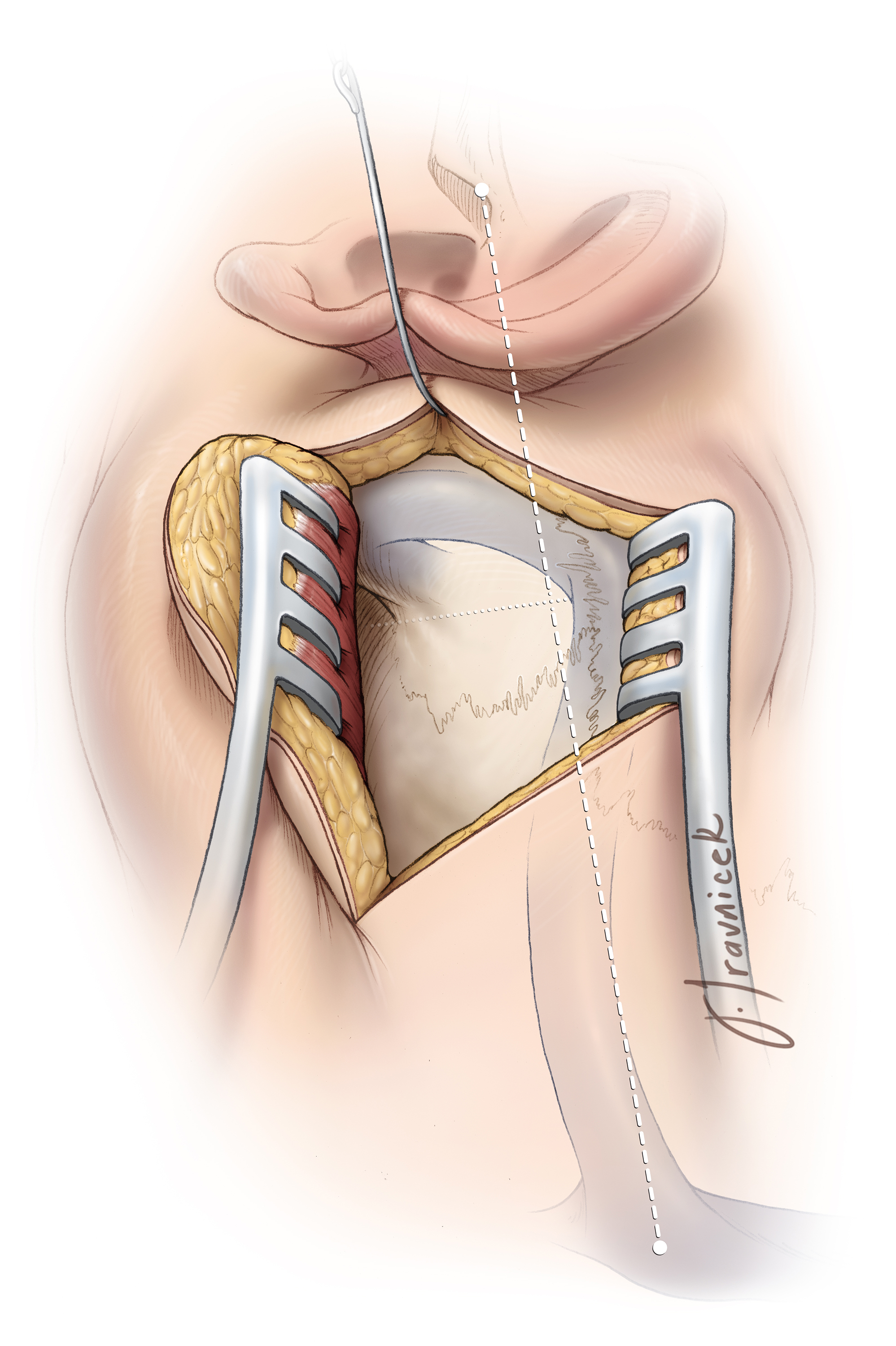
Figure 9: Identification of the transverse-sigmoid junction will guide placement of a burr hole just below this junction. The burr hole is created where the transverse sinus (the hashed line in white connecting the inion to the root of the zygoma) crosses the sigmoid sinus (the hashed in black, marking the mastoid groove).
This burr hole often barely exposes the medial and inferior walls of the junction of the dural venous sinuses. The asterion is not a constant finding (especially in older crania), and a burr hole over the asterion often exposes the entire width of the transverse sinus, placing this structure at risk of injury. Please note the use of a cerebellar retractor and fishhooks to enhance bone exposure through the retraction the myocutaneous flap and scalp, respectively.

Figure 10: Burr hole and craniotomy (TN: trigeminal neuralgia; HS: hemifacial spasm; GN: glossopharyngeal neuralgia; AN: acoustic neuroma). The location of the burr hole and the craniotomy for HS and GN may be situated slightly more caudally; this modification is discussed in their corresponding chapters.
I place a single burr hole at the edge of the junction of dural sinuses to orient myself regarding the desired location of the planned craniotomy/ectomy. The exact location of these dural sinuses is slightly variable, and the initial burr hole should be placed with caution; it may be enlarged in the correct direction when the initial small pilot burr hole is done.
I dissect the dura from the inner surface of the skull bone, paying special attention to detaching the edge of the dural sinuses, especially the sigmoid sinus. The sigmoid sinus may be embedded into the inner cortical bone and should be left alone to avoid a tear in its wall; the roof of the sigmoid sinus may be ‘egg-shelled” and removed in a second step after elevation of the bone flap. In the case of microvascular decompression operations, the size of the craniotomy or craniectomy is often small, about 1.5-2 times the size of a quarter coin.
The first limb of the osteotomy extends posteriorly, inferiorly, then anteriorly, and stops short of the sigmoid sinus’s posterior border. The second bony cut is performed over the posterior edge of the sigmoid sinus in a cranio-caudal direction. A craniotomy should be avoided in older patients and in those with an adherent dural surface to the inner skull bone. When in doubt, plan a craniectomy as it is a safer option.

Figure 11: The extended retromastoid craniotomy: Exposing the posterior half of the sigmoid sinus is the cardinal step to expand the operative corridor through this approach.
After I complete the craniotomy and elevate the bone flap, I drill a portion of the mastoid bone, exposing the posterior edge of the sigmoid sinus along its length. I also bevel out the outer bony edge in the area and remove any overhanging bone to improve lateral mobilization or rotation of the sigmoid sinus during reflection of the dura. This maneuver allows a more anterolateral operative trajectory toward the CP angle, potentially minimizing the need for cerebellar retraction while allowing more flexible operative working angles.
The bone over the sigmoid sinus is best removed by careful drilling and “egg-shelling” since the wall of this dural sinus is often very adherent to the inner aspect of the calvarium. The drill’s handle should move in the direction of its rotating burr to avoid its inadvertent slippage over bony edges.

Figure 12: Kerrison rongeurs remove the “egg-shell” of bone over the sigmoid sinus. The Kerrison’s “mouth” should be pointed away from the sinus to avoid a tear in the sinus wall. If excessive bleeding is encountered and a small tear in the wall of the sinus is detected, bone wax may be used to seal the hole against the edge of the mastoid bone. Indiscreet impaction of hemostatic material such as gelfoam into the sinus should be avoided to prevent sinus thrombosis. The emissary vein may be found at this juncture and coagulated.

Figure 13: Mastoid air cells should be well waxed, both after completing the craniotomy and later in the procedure at the end of dural closure. The epidural space should then be generously irrigated to prevent any debris (such as bone dust) from entering the intradural space. This maneuver can decrease the risk of postoperative aseptic meningitis.
OPERATIVE CORRIDORS: THE SUPRALATERAL AND INFRALATERAL ROUTES
As discussed previously, purely medial retraction of the cerebellar hemisphere parallel to CN VIII places this sensitive nerve at risk of retraction injury. Therefore, I use two operative corridors initially to reach the CP angle: the supralateral and the infralateral routes.
The Supralateral Route for Lesions Posterior and Superior to the CN’s VII/VIII Complex

Figure 14: The dural incisions for the supralateral route parallel the sigmoid and transverse sinuses. The dural incision is performed a few millimeters away from the edge of the venous sinuses (left image). The retraction sutures along the sigmoid sinus dura gently mobilize and rotate this sinus anteriorly and laterally in order to expand the lateral aspect of the operative corridor toward the CP angle (right image).
During opening of the dura, if a venous sinus tear is evident or a venous lake is encountered, this laceration or opening into the sinus may be sutured primarily over a small piece of muscle. Bipolar coagulation of the tear usually retracts the dural edges further, increasing the size of the laceration and compounding the problem.
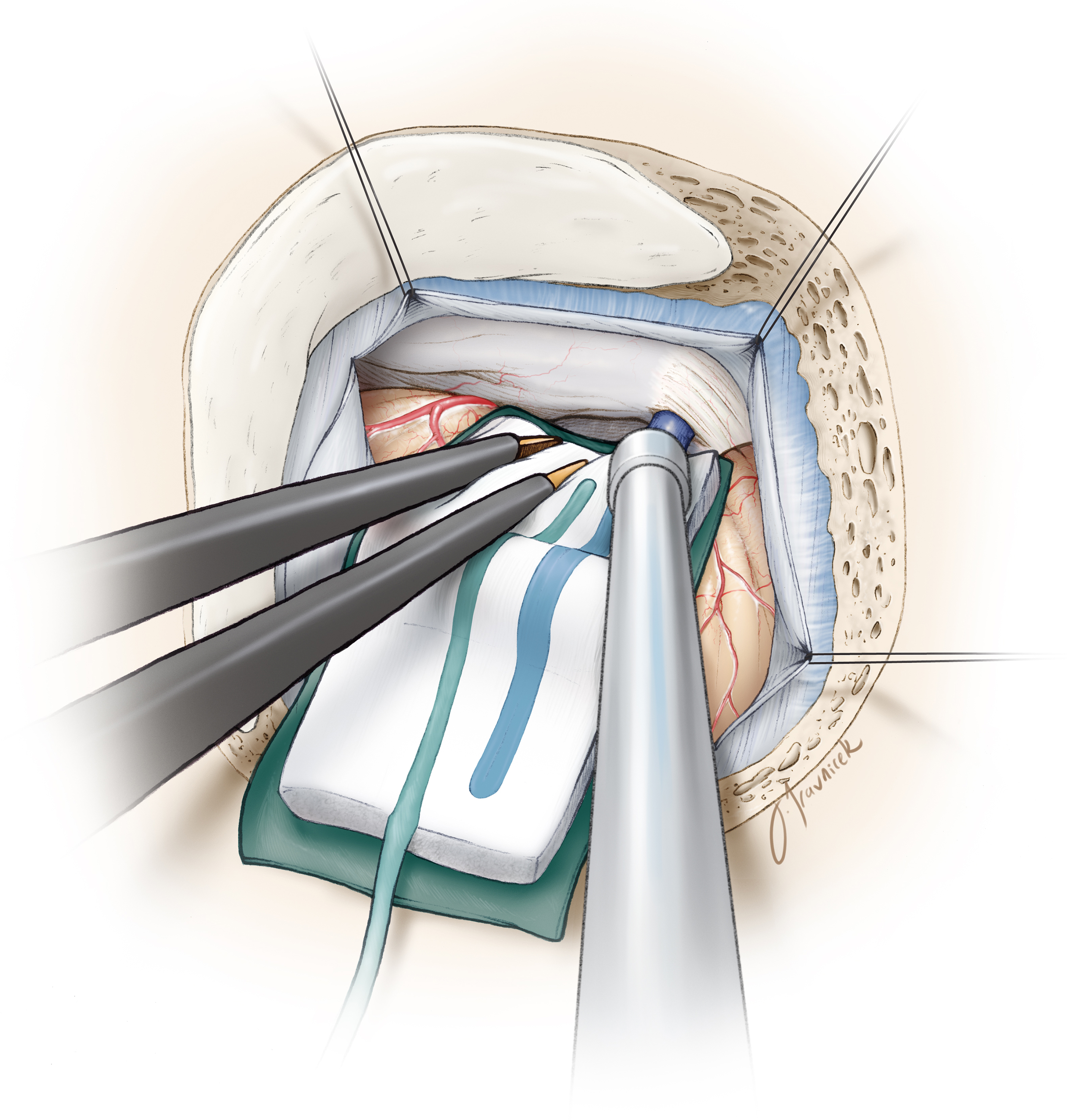
Figure 15: Inframedial cerebellar retraction allows exposure of lesions within the CP angle, superior and posterior to CN’s VII/VIII. The CSF drainage at the beginning of the procedure relaxes the cerebellum and substantially simplifies this step.
A piece of glove (cut slightly larger than the cottonoid) acts as a rubber dam and protects the cerebellar hemisphere from potential injury caused by friction from the cottonoid’s surface while “going around” the hemisphere. I advance the cottonoid parallel to the junction (groove) of the tentorium and petrous apex, toward the petrous side. Identification of the petro-tentorial junction prevents
- an unintentional exposure (and resultant tear and bleeding) of the supracerebellar bridging veins superiorly, and
- a retraction vector directly parallel to the CN VII/VIII complex, which would place the patient’s hearing at risk.
Strategic placement of the suction apparatus will allow dynamic retraction of the lateral hemisphere and selective exposure of the operative field at the level of CN V’s root entry zone, obviating a need to employ fixed rigid retractors and to sacrifice the superior petrosal vein.
Retromastoid Craniotomy: MVD for Trigeminal Neuralgia
The Infralateral Route for Lesions Anterior and Inferior to the CN's VII/VIII Complex
The dura is incised parallel to the sigmoid sinus and the floor of the posterior fossa. The edges of the dura are tacked up against the craniotomy margins using three silk sutures, and the same techniques are applied as mentioned above in the section related to the supralateral route.

Figure 16: Supramedial cerebellar retraction: A piece of glove (cut slightly larger than the cottonoid patty) acts as a rubber dam. It protects the cerebellar hemisphere against the rough surface of the cottonoid as the rubber dam slides over the cerebellum while dissection is continued to expose the cerebellopontine angle (left image). I identify the junction of the petrous bone and the floor of posterior fossa (P, right intraoperative image) and advance the cottonoid over the rubber dam near the turn of the petrous bone toward the lower cranial nerves.
The vector of retraction is parallel to CN IX. The shaft of the suction apparatus is used to mobilize the cerebellar hemisphere in a dynamic fashion during the dissection process. Along with generous sharp dissection of the regional arachnoid membranes within the inferior CP angle, this maneuver minimizes the risk of cranial nerve and cerebellar injury.
The operator can easily get disoriented and early identification of petrous-tentorial junction (supralateral route) and petrous-posterior fossa floor junction (infralateral route) avoids any surprise or confusion.
Retromastoid Craniotomy: MVD for Hemifacial Spasm
Closure

Figure 17: Dural closure
The dura is approximated primarily. I do not perform a watertight dural closure and have experienced a very low rate of CSF leak for microvascular decompression operations. These procedures are pristine and associated with a small risk of increased CSF pressures postoperatively.
However, a watertight dural closure is mandatory for operations involving resection of tumors. Mastoid air cells are rewaxed thoroughly (“wax in, wax out”), and the bone flap is replaced or a methyl methacrylate cranioplasty is performed. The muscle and scalp are closed in anatomical layers.
Postoperative Considerations
After surgery, patients are usually admitted to the ICU for an overnight stay for observation and then transferred to the regular ward for a couple of days before they can be discharged home. Special attention should be paid to hemodynamic parameters, the neurologic examination, and wound care. Steroids are administered to prevent aseptic meningitis and minimize postoperative nausea and headaches.
Occasionally, delayed facial palsy and hearing loss may occur, especially after MVD for hemifacial spasm and resection of epidermoid tumors. These deficits are most often temporary and respond well to a tapered dose of dexamethasone of 1 week in duration.
Other Considerations to Expand the Operative Corridor: The Transtentorial Route
The retromastoid and supracerebellar routes may be combined to expose the tentorium. A wide excision of the tentorium would allow access to the ventrolateral petroclival area and posterior basal temporal lobe (posterior parahippocampus) as well as middle fossa floor. Moreover, this pathway would facilitate resection of posterior fossa tumors extending into the middle fossa in one stage while avoiding a second operation through the supratentorial corridor. I will discuss these modifications in the chapter related to supracerebellar craniotomy.
Alternative Incisions for Retromastoid Craniotomy

Figure 18: The linear incision is most commonly used for microvascular decompression surgery and exposing small CP angle tumors. The linear incision is marked 1/3 above and 2/3 below the transverse sinus. The approximate location of the transverse sinus is demonstrated using the short crossing line.
Shortcomings of the Linear Incision for Retromastoid Craniotomy
Pearls and Pitfalls
- The extended retromastoid craniotomy is the flexible workhorse approach for resection of lesions within the CP angle.This approach can sometimes obviate the need for more involved petrosal osteotomies.
- The cerebellum should be retracted only parallel to the direction of CN’s V and IX to avoid direct traction on CN VIII. Sharp arachnoid dissection and strategic dynamic cerebellar retraction will facilitate cerebellar mobilization without placing the cranial nerves at risk.
For additional illustrations of a retrosigmoid approach to the internal auditory canal and cerebellopontine angle, please refer to the Jackler Atlas by clicking on the image below:

For additional illustrations of a retrosigmoid approach to the jugular foramen, please refer to the Jackler Atlas by clicking on the image below:

References
Cohen-Gadol AA. Microvascular decompression surgery for trigeminal neuralgia and hemifacial spasm: Nuances of the technique based on experiences with 100 patients and review of the literature. Clin Neurol Neurosurg. 2011;113:844-853.
Please login to post a comment.