Surgery for Acoustic Neuroma: Middle Fossa Approach


Resection of an Acoustic Neuroma through the Middle Cranial Fossa Approach
For general considerations, clinical presentation, and evaluation of vestibular schwannomas (VSs), please refer to the Retrosigmoid Approach for Acoustic Neuroma chapter.
Please note the relevant information for patients with acoustic neuroma is presented in another chapter. Please click here for patient-related content.
Indications for the Middle Cranial Fossa Approach
The main indications for the middle cranial fossa (MCF) approach include removal of a small predominately intracanalicular VS, exposure of the labyrinthine and upper tympanic segments of the facial nerve for decompression, vestibular nerve section, and repair of superior semicircular canal dehiscence.
Historically, the MCF approach offers some of the highest hearing preservation rates, but it can also place the facial nerve between the surgeon and the tumor, potentially leading to a higher risk of postoperative facial weakness. In some cases, this configuration results in the need for blind dissection.
This route also requires some retraction on the temporal lobe, with the ensuing potential risk of postoperative seizures and speech disturbances, while providing a limited view of the cerebellopontine (CP) angle.
The MCF approach is poorly tolerated by elderly patients because extradural dissection of the adherent dura in this specific population may be difficult. This approach is suggested for younger patients with smaller tumors that harbor the predominant component of their growth within the internal auditory canal (IAC). Specifically, tumors that involve the fundus of the IAC, a location to which access and visualization are restricted during the retrosigmoid trajectory, are good candidates for the MCF route.
Overall, the MCF approach provides a limited working window into the posterior fossa. This limitation is complicated by the presence of the facial nerve within the surgeon’s view and restricts the surgeon’s ability to resect large tumors. The retrosigmoid option, on the other hand, provides a more panoramic view of the tumor in the CP angle cisterns and its relationship to the surrounding neurovascular structures.
Preoperative Considerations
The MCF approach is not favored for tumors with significant extracanalicular extension (>1−2 cm) because of the associated poor visualization of the CP angle and brainstem. Intraoperative navigation based on a high-resolution CT of the temporal bone is used for localization of the IAC and the adjacent temporal bone structures.
Neurophysiologic monitoring of the facial nerve using electromyography and brainstem auditory evoked responses (BAERs) is considered routine.
Operative Anatomy
The IAC is approached through the floor of the MCF. A subtemporal craniotomy provides the corridor to elevate the dura from the floor of the MCF, and the IAC is initially localized based on anatomic landmarks.
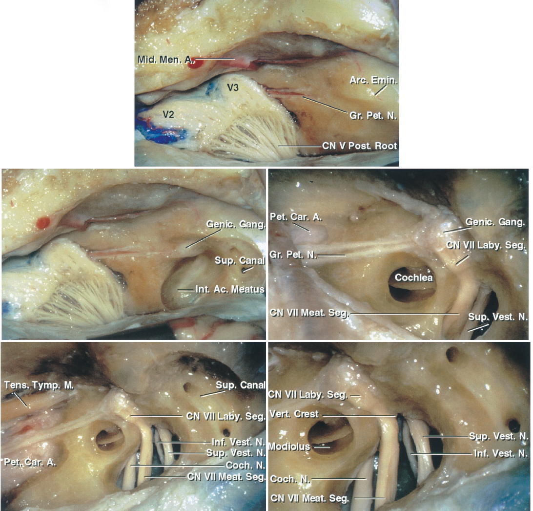
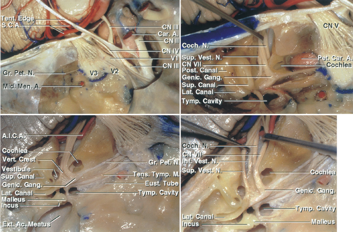
Figure 1: The MCF approach to the right IAC is shown. The subtemporal dura has been dissected from the middle fossa floor to expose the middle meningeal artery, the greater superficial petrosal nerve, and the arcuate eminence (top image). Part of the bone over the roof of the IAC has been removed. The bone over the arcuate eminence has been drilled to identify the exact location of the superior semicircular canal (left middle image). An enlarged version of the left middle image with additional bone removal exposes the cochlea, located below the middle fossa floor in the angle between the facial and greater petrosal nerves. The IAC is unroofed (right middle image). The semicircular canals are posterolateral and the cochlea is anteromedial to the IAC (left lower image). An enlarged view of the left lower image in included (right lower image). Note that the vertical crest (Bill’s bar) divides the facial and superior vestibular nerves at the IAC. The superior and inferior vestibular nerves are located caudally and the facial and cochlear nerves rostrally within the IAC. The labyrinthine segment of the facial nerve travels superolaterally to the cochlea (images courtesy of AL Rhoton, Jr).
Click here to view the interactive module and related content for this image.
Figure 2: Additional anatomy of the right middle fossa floor is shown. The greater superficial petrosal nerve and the middle meningeal artery in relation to the cavernous sinus are shown (left upper image). The middle fossa floor contents are identified, including the cochlea, semicircular canals, petrous carotid artery, and the facial, cochlear, and superior vestibular nerves in the IAC. The superior semicircular canal is prominent under the arcuate eminence. The cochlear nerve courses underneath the facial nerve to join the cochlea, which is situated above the lateral genu of the petrous carotid in the angle between the pregeniculate facial and greater petrosal nerves (right upper image). This anatomy is further elaborated upon to identify the IAC, cochlea, vestibule, semicircular canals, tympanic cavity, and external meatus. The vestibule is posterolateral and the cochlea is anteromedial to the fundus of the IAC (left lower image). The configuration of the nerves within the IAC from a superior view is demonstrated (right lower image)(images courtesy of AL Rhoton, Jr).
RESECTION OF VESTIBULAR SCHWANNOMA VIA THE MIDDLE CRANIAL FOSSA APPROACH
Before final positioning of the patient on the operating room table, I place a lumbar drain. Early cerebrospinal fluid (CSF) drainage is necessary to avoid temporal lobe injury during the lobe’s extradural retraction. Often 40 to 60 cc of CSF is drained gradually (in 10 cc aliquots) until the lobe is relaxed and safely mobilized for adequate exposure of the petrous ridge.
I prepare the lower quadrant of the patient's abdomen for harvesting adipose grafts used for filling the dural defect at the end of tumor removal.
The patient is positioned supine on the operating room table. A shoulder roll is placed under the patient's contralateral shoulder and the head rotated until the sagittal suture is parallel to or minimally angled from the floor. If the patient has a supple neck, he or she can tolerate up to 70 degrees of rotation. If the patient has a rigid neck, the size of the shoulder roll may be increased to compensate for the limitation in neck rotation. For obese patients with relatively immobile necks, the lateral position is appropriate to avoid interruption of adequate venous return and nonphysiologic neck postures that can lead to postoperative neck pain.

Figure 3: The patient’s position with the zygoma as the highest point in the operative field is illustrated. The single pin of the skull clamp often must be placed on the patient’s forehead to avoid interference of the pins with the incision. The vertex of the patient's head is tilted slightly toward the floor. This maneuver maximizes the effect of gravity retraction on the temporal lobe.
A line connecting the single pin with the midpoint between the opposite two pins (swivel rocker arm) must always cross the equator of the patient's head to prevent skull clamp fixation failure during surgery.
I use a linear incision similar to the one used for the subtemporal approach.

Figure 4: The linear incision, as outlined here in red (upper illustration), is adequate and heals most effectively. This incision starts near the inferior edge of the zygomatic arch, just in front of the superficial temporal artery that may be palpated during planning the incision. The incision extends cranially toward the vertex, just above the superior temporal line. The linear incision mobilizes enough scalp and temporal muscle flaps to provide adequate skull exposure and obviates the need for more extensive incisions. Upon completion of the incision, the scalp is undermined and the attachments of the temporalis muscle to the superior temporal line are disconnected beyond the incision. This maneuver significantly expands the bone exposure through the linear incision.
Adequate muscle dissection will expose the posterior root of the zygomatic arch. One must not dissect so low as to violate the mandibular joint or the external auditory canal.
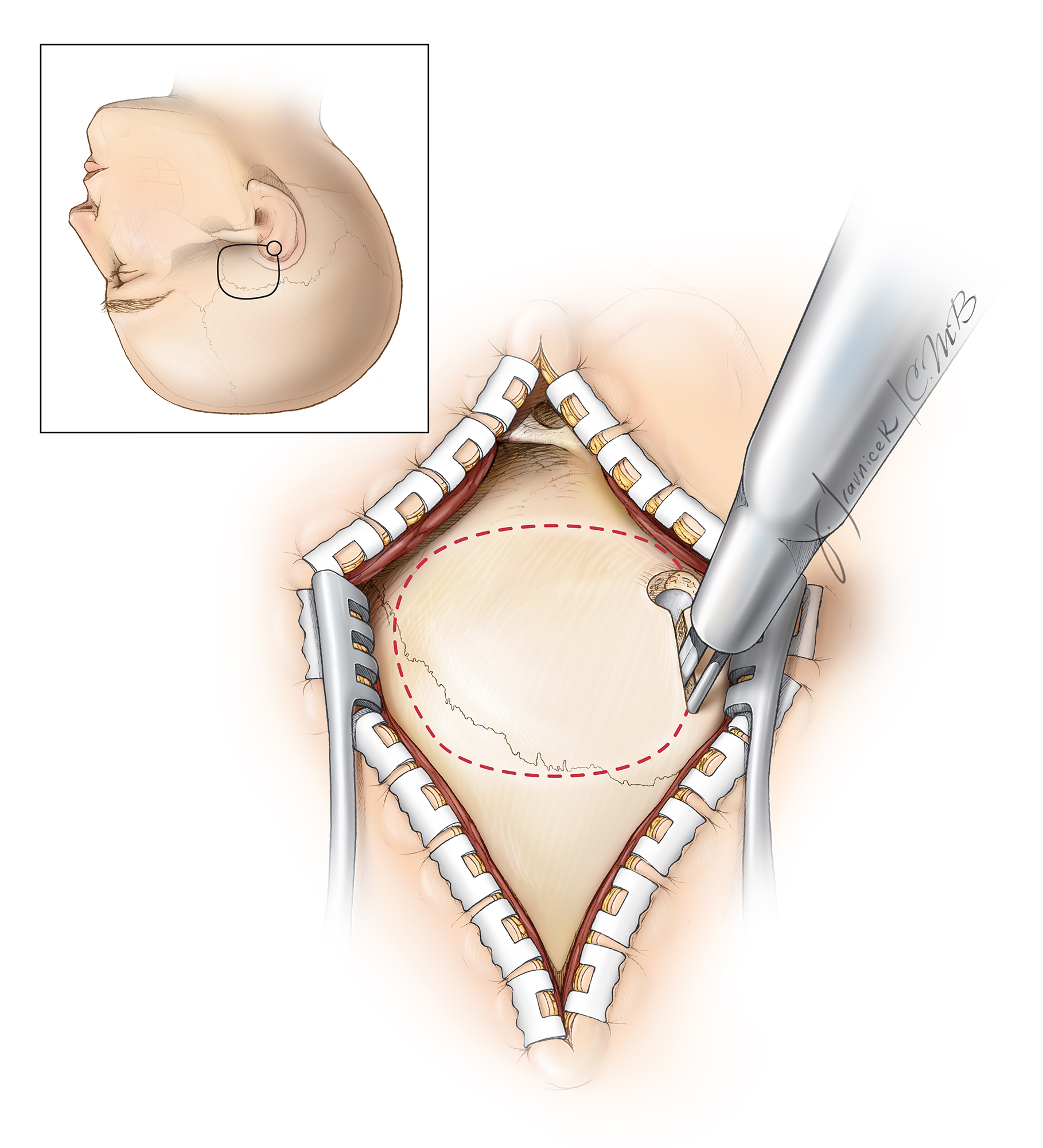
Figure 5: Craniotomy through a linear incision is illustrated. In this case, the fibers of the temporalis muscle are split longitudinally and the muscle attachments along the superior temporal line are disconnected. When compared with the horseshoe incision, the posterior extent of exposure may be slightly compromised. Regardless which incision is used, the width of the craniotomy is about 4 cm and 2/3 anterior and 1/3 posterior to the external auditory canal. The root of the zygoma is exposed. Intraoperative navigation can help with creation of the craniotomy relative to the the IAC.
More burr holes may be used, if necessary, to preserve the integrity of the dura during the elevation of the bone flap. Alternatively, the entire set of bone cuts may be completed using a diamond drill. Preservation of the dura’s integrity is crucial to avoid injury to the lobe during the later stages of extradural dissection along the middle fossa floor.
Next, the footplate of the craniotome is used to complete the craniotomy. The bone flap is elevated with its inferior edge parallel and as close as possible to the floor of the middle fossa. The zygomatic arch defines the level of the middle fossa floor and may be used as a reference; this floor slopes slightly upward from an anterior-to-posterior direction.

Figure 6: After the craniotomy flap is elevated, the remaining base of the temporal squama is reduced flush with the floor of the middle fossa. This goal can be accomplished using rongeurs or a drill with a side-cutting burr. Air cells are often exposed at this step of the operation and must be thoroughly obliterated with bone wax to prevent creation of a CSF fistula. The superior edge of the zygomatic arch may also be drilled to provide an unobstructed view of the middle fossa floor, but this is rarely necessary.

Figure 7: Additional removal of CSF through the lumbar drain relaxes the brain in preparation for its mobilization. Once the floor of the middle fossa is visible, I use a #1 Penfield dissector to detach the dura from the lateral aspect of the petrous bone. A self-retaining retractor may be placed on the dura to protect it during drilling. The remaining bone of the squama and the bony gyrations along the lateral middle fossa floor are drilled completely flush with the lowest level of the floor to improve the operative working angles while minimizing temporal lobe retraction.

Figure 8: The dura over the floor of the anterior aspect of the middle fossa is now elevated. The middle meningeal artery (red arrow, lower image), entering through the foramen spinosum, is identified. The artery may need to be coagulated on its dural side and transected. Next, I pack the foramen with bone wax and oxidized cellulose. Stripping of the dura anteriorly must stop at this point to avoid direct injury to the greater (GSPN)(yellow arrow) and lesser (LSPN) superficial petrosal nerves, potentially leading to dry eyes. Inadvertent traction on the GSPN also places the facial nerve at risk. The surgeon can minimize the risk of this type of injury by lifting the dura in a posterior-to-anterior direction.
The origin of the GSPN can be identified posteriorly at the hiatus; the dura is then stripped anteriorly in line with the nerve to prevent dislocation of the nerve out of its groove. The second caveat to the epidural exposure is that the surgeon must find the “true edge” of the petrous ridge. The superior petrosal sinus forms the petrosal groove along the superior aspect of the petrous ridge. The upper edge of this groove is often mistaken for the petrous ridge, resulting in an inadequate elevation of the dura. Proper elevation of the dura along the ridge allows the retractor’s blade to readily rest against the petrous ridge and optimally retract the dura without slippage.

Figure 9: The next step is to identify the meatal plane—the area of bone covering the IAC. Numerous methods of locating the meatal plane have been described. The Garcia-Ibanez technique relies on the relationship between the GSPN and the arcuate eminence, usually located at an angle of 120 degrees. Bisection of this angle provides the general location of the IAC and a starting point for drilling the petrous ridge. Similarly, the Fisch technique uses an approximately 60-degree angle between the long axis of the arcuate eminence and the meatal plane to estimate the location of the IAC. The relevant anatomy of the middle fossa floor is illustrated. A House-Urban retractor is used for elevation of the temporal lobe.

Figure 10: The anatomy of the middle fossa floor is widely variable, and the arcuate eminence is not always a reliable locator of the superior semicircular canal. As a general rule, the IAC courses at a 45-degree angle from a line that runs from the arcuate eminence perpendicular to the petrous ridge; this is my preferred method to locate the IAC. Intraoperative navigation confirms this anatomic localization. Once the presumed location of the IAC is identified, its roof is removed using a 3-mm coarse diamond burr along with continuous irrigation. The generous use of irrigation removes bone dust and decreases the likelihood of thermal injury to the underlying nerves. The bone removal begins at the petrous ridge, exposing the proximal dura over the IAC.

Figure 11: These are other methods of localizing the IAC. The right-sided superior semicircular canal is identified either by image guidance or, more accurately, via blue-lining of the canal (upper image, blue arrows). The IAC (black lines) bisects the angle between the course of the GSPN (yellow arrows) and the route of the superior semicircular canal. These anatomic relationships vary, and more than one method of localization should be employed. The anatomy of the left middle fossa floor is demonstrated in the lower image (courtesy of AL Rhoton, Jr). All of the intraoperative photos and illustrations refer to a right-sided approach, whereas the above anatomic photo refers to a left temporal bone.

Figure 12: As the meatal bone is removed in layers, the curved shape of the dura as it enters the IAC verifies the location of this canal. Bone removal proceeds from a medial-to-lateral direction, skeletonizing the medial half of the IAC 270 degrees in its circumference. Skeletonization is less complete in the lateral half of the IAC to avoid injury to the cochlea or superior semicircular canal ampulla. The surgeon must avoid entry into the cochlea while drilling lateral to the IAC; the cochlea is located under the apex of the angle formed by the GSPN and the superior semicircular canal.
As bone resection proceeds laterally, a 0.5-mm to 1.0-mm diamond burr is used, and the labyrinthine segment of the facial nerve and the vertical crest (Bill’s bar) become visible through the thinned bone. The remaining eggshell of bone over the IAC is removed using an angled microcurette.
INTRADURAL PROCEDURE
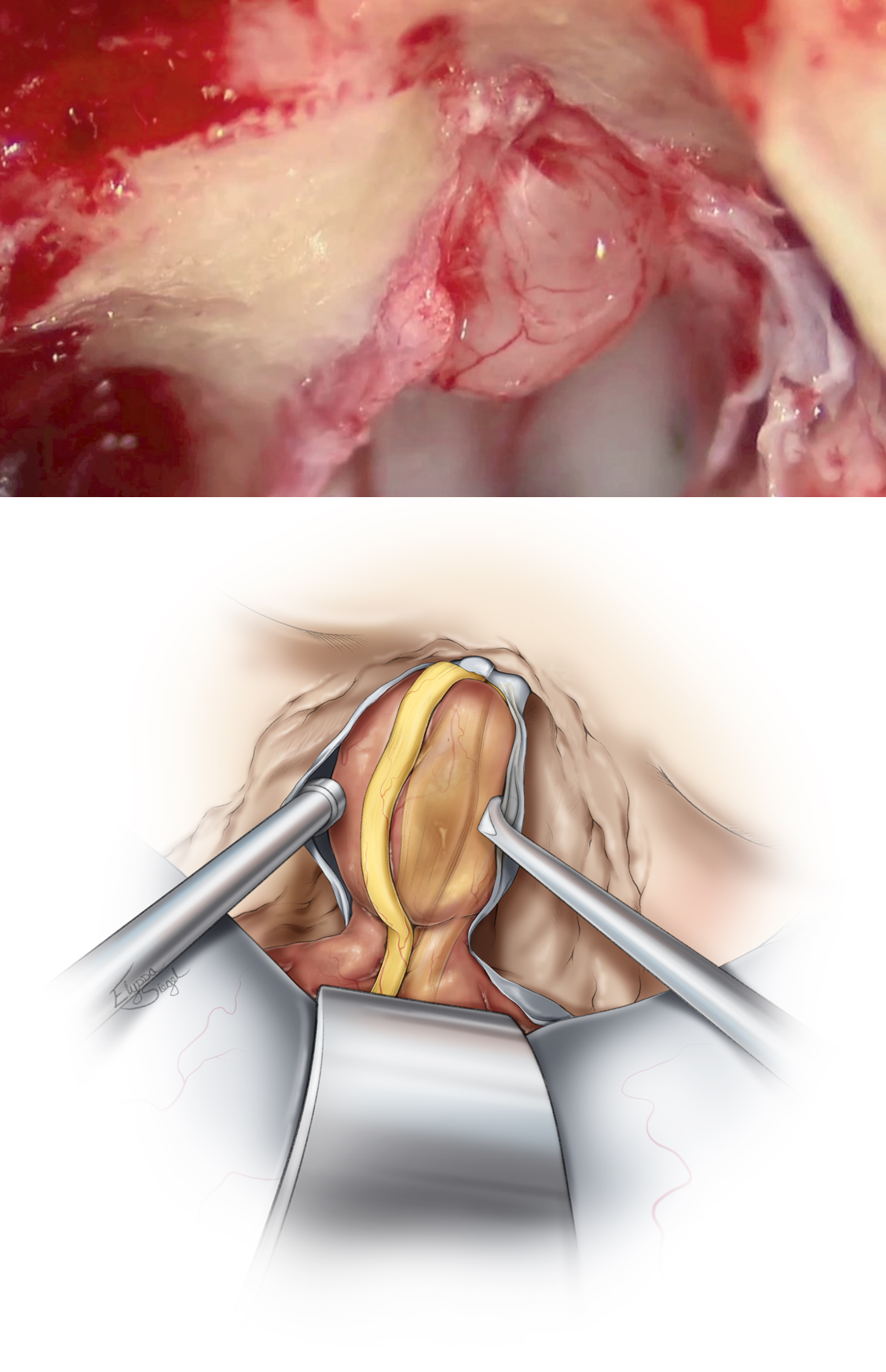
Figure 13: A T-shaped dural incision is made, with the first incision parallel and just inferior to the superior petrosal sinus. The location of the facial nerve in the IAC is then identified transdurally via electrical stimulation. The second limb of the incision is made parallel to the IAC away from the location of the facial nerve that commonly lies within the anterior aspect of the IAC, so the dura is typically incised posteriorly. The two dural flaps are reflected and secured, exposing the contents of the IAC.
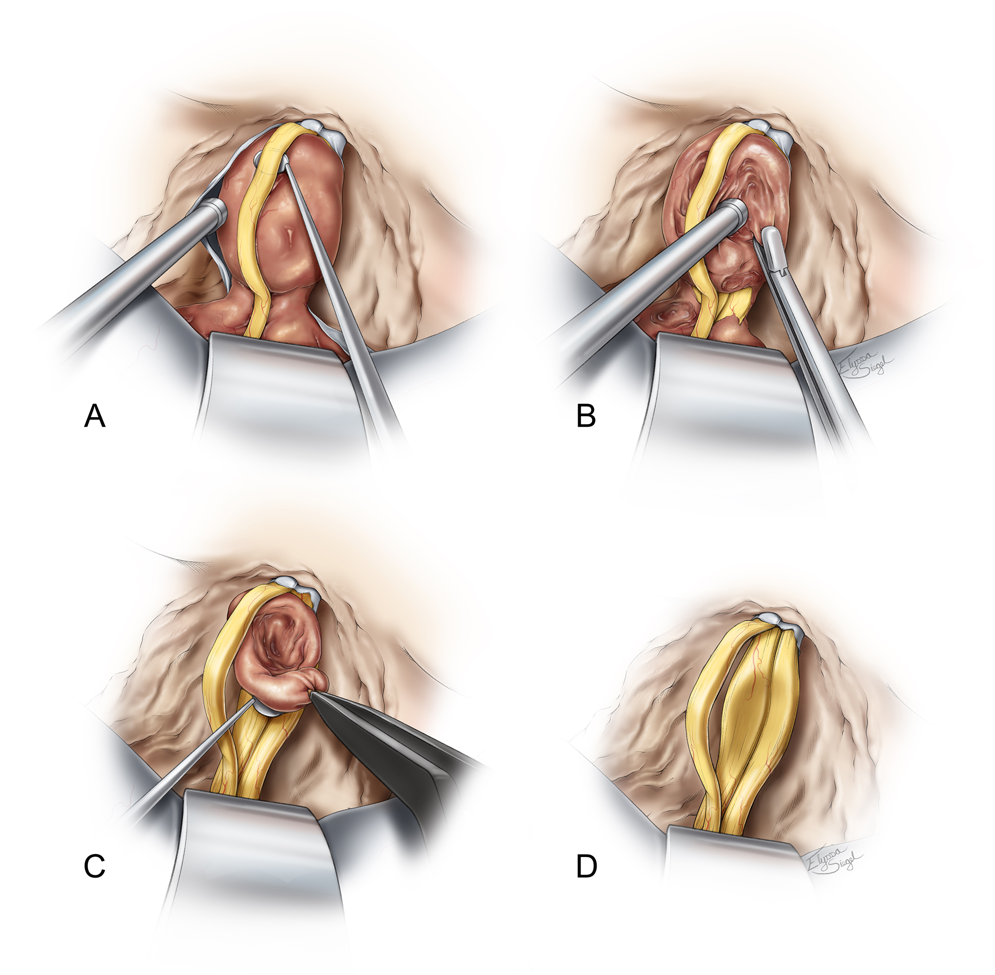
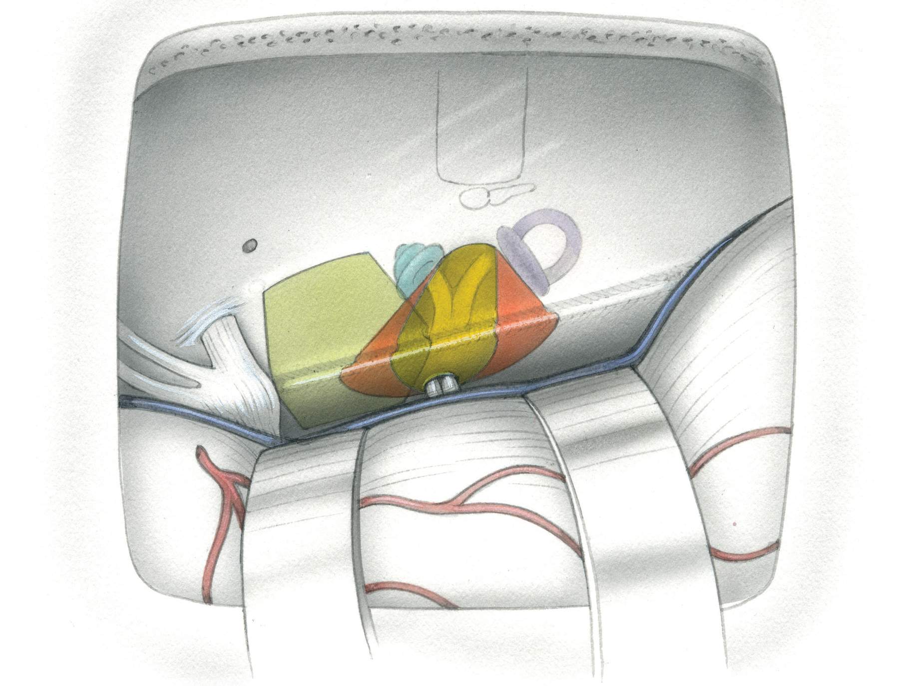
Figure 14: The facial nerve and its edges are precisely identified with electrical stimulation and visually under high magnification of the microscope. The schwannoma capsule is opened away from the facial nerve and the tumor is internally debulked. A fine dissector is used to develop a plane between the tumor and the facial/cochlear nerves. Dissection is performed in a medial-to-lateral direction to minimize injury to the tiny fascicles of the cochlear nerve found at the lateral extent of the IAC, entering the modiolus.
The affected vestibular nerve may be sectioned at the fundus to create some slack for tumor manipulation. The facial nerve is stimulated prior to this section to ensure its preservation. When the tumor is more thoroughly dissected from the facial and cochlear nerves, the vestibular nerve is sectioned proximally and the tumor is removed. Any alternation in the BAERs should alert the surgeon to adjust his or her maneuvers, because there could be too much traction on the cochlear nerve or stretch on the labyrinthine artery.
Bipolar coagulation is avoided and irrigation fluid is used to keep the operative field visible. These maneuvers can improve the outcomes for hearing preservation.

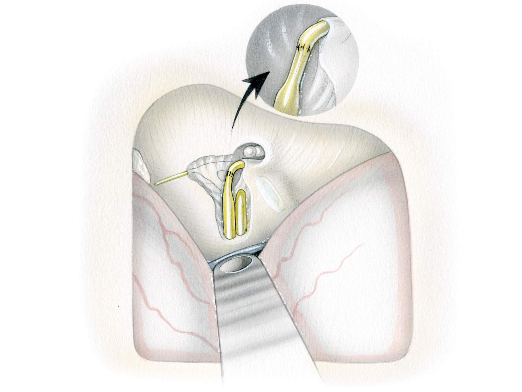
Figure 15: The final result of tumor resection and the anatomically intact facial nerve are shown.
Closure
Primary dural closure is not possible in this area and alternative methods are needed. Adipose tissue with its globular texture is one of the best barriers against CSF leakage. Strips of adipose tissue are placed across the dural opening to seal the defect. Before placement of the adipose grafts, all air cells must be meticulously waxed. Alternatively, a piece of temporalis muscle in conjunction with temporalis fascia may be used to cover the dural defect over the IAC.
The bone flap is replaced and secured using miniplates, and the rest of closure is conducted in standard fashion.
A lumbar drain is used to drain 8 cc/hour of CSF for 48 hours after surgery. A computed tomography scan the morning after surgery should exclude significant pneumocephalus before the drain is utilized. Patients are mobilized as soon as possible.
Contributor: Andrew R. Conger, MD, MS
DOI: https://doi.org/10.18791/nsatlas.v5.ch08.3
For additional illustrations of combined transpetrosal-middle fossa approaches, please refer to the Jackler Atlas by clicking on the image below:

For additional illustrations of the extended middle fossa approach to the cerebellopontine angle, please refer to the Jackler Atlas by clicking on the image below:
For additional illustrations of facial nerve repair, please refer to the Jackler Atlas by clicking on the image below:
For additional illustrations of hypoglossal-facial anastomosis, please refer to the Jackler Atlas by clicking on the image below:

For additional illustrations of the middle fossa approach to the internal auditory canal, please refer to the Jackler Atlas by clicking on the image below:

For additional illustrations of tumor growth patterns, please refer to the Jackler Atlas by clicking on the image below:
Some of the materials included in this chapter have also previously been described in the following articles:
Ansari SF, Terry C, Cohen-Gadol AA. Surgery for vestibular schwannomas: a systematic review of complications by approach. Neurosurg Focus. 2012;33:E14.
Kulwin CG, Cohen-Gadol AA. Technical nuances of resection of giant (> 5 cm) vestibular schwannomas: pearls for success. Neurosurg Focus. 2012;33:E15.
References
Angeli S. Middle fossa approach: indications, technique, and results. Otolaryngol Clin North Am. 2012;45:417-438.
Briggs RJ, Shelton C, Kwartler JA, Hitselberger W. Management of hydrocephalus resulting from acoustic neuromas. Otolaryngol Head Neck Surgery. 1993;1020-1024.
Charpiot A, Tringali S, Zaouche S, Ferber-Viart C, Dubreuil C. Perioperative complications after translabyrinthine removal of large or giant vestibular schwannoma: outcomes for 123 patients. Acta Otolaryngol. 2010;130:1249-1255.
Diaz Day J. The middle fossa approach and extended middle fossa approach: technique and operative nuances. Neurosurgery. 2012;70 (2 Suppl Operative):192-201.
Falcioni M, Fois P, Taibah A, Sanna M. Facial nerve function after vestibular schwannoma surgery. J Neurosurg. 2011;115:820-826.
Fisch U. Transtemporal surgery of the internal auditory canal: report of 92 cases, technique indications, and results. Adv Otorhinolaryngol. 1970;17:203–240.
Fundova P, Charabi S, Tos M, Thomsen J. Cystic vestibular schwannoma: surgical outcome. J Laryngol Otol. 2000;114:935-939.
Garcıa-Ibanez E, Garcıa-Ibanez JL. Middle fossa vestibular neurectomy: a report of 383 cases. Arch Otolaryngol Head Neck Surg. 1980;88:486-490.
Gardner G, Robertson JH. Hearing preservation in unilateral acoustic neuroma surgery. Ann Otol Rhinol Laryngol. 1988;97:55-66.
Gerganov VM, Pirayesh A, Nouri M, Hore N, Luedemann WO, Oi S, et al. Hydrocephalus associated with vestibular schwannomas: management options and factors predicting the outcome. J Neurosurg. 2011;114:1209-1215.
House WF. Surgical exposure of the internal auditory canal and its contents through the middle cranial fossa. Laryngoscope. 1961;71:1363-1385.
Jackler RK, Pitts LH. Selection of surgical approach to acoustic neuroma. 1992. Neurosurg Clin N Am. 2008;19:217-238, vi.
Mamikoglu B, Wiet RJ, Esquivel CR. Translabyrinthine approach for the management of large and giant vestibular schwannomas. Otol Neurotol. 2002;23:224-227.
Pirouzmand F, Tator CH, Rutka J. Management of hydrocephalus associated with vestibular schwannoma and other cerebellopontine angle tumors. Neurosurgery. 2001;48:1246-1253; discussion 1253-1244.
Raslan AM, Liu JK, McMenomey SO, Delashaw JB, Jr. Staged resection of large vestibular schwannomas. J Neurosurg. 2012;116:1126-1133.
Rhoton A. The cerebellopontine angle and posterior cranial fossa nerves by the retrosigmoid approach. Neurosurgery. 2000; 47(suppl 3):93-129
Rhoton A. Anatomy and surgical approaches of the temporal bone and adjacent areas. Neurosurgery. 2007;61(suppl 4): S1-250.
Rivas A, Boahene KD, Bravo HC, Tan M, Tamargo RJ, Francis HW. A model for early prediction of facial nerve recovery after vestibular schwannoma surgery. Otol Neurotol. 2011;32:826-833.
Roche PH, Ribeiro T, Fournier HD, Thomassin JM. Vestibular schwannomas: complications of microsurgery. Prog Neurol Surg. 2008;21:214-221.
Samii M, Gerganov, VM. Surgery of Cerebellopontine Lesions. 2013.
Samii M, Gerganov VM, Samii A. Functional outcome after complete surgical removal of giant vestibular schwannomas. J Neurosurg, 2010;112:860-867.
Samii M, Matthies C. Management of 1000 vestibular schwannomas (acoustic neuromas): surgical management and results with an emphasis on complications and how to avoid them. Neurosurgery. 1997;40:11-21; discussion 21-13.
Sampath P, Rini D, Long DM. Microanatomical variations in the cerebellopontine angle associated with vestibular schwannomas (acoustic neuromas): a retrospective study of 1006 consecutive cases. J Neurosurg. 2000;92:70-78.
Sanna M, Taibah A, Russo A, Falcioni M, Agarwal M. Perioperative complications in acoustic neuroma (vestibular schwannoma) surgery. Otol Neurotol. 2004;25:379-386.
Silva J, Cerejo A, Duarte F, Silveira F, Vaz R. Surgical removal of giant acoustic neuromas. World Neurosurg 2012, 77;731-735.
Sriskandan N, Connor SE. The role of radiology in the diagnosis and management of vestibular schwannoma. Clin Radiol. 2011;66:357-365.
Tanaka Y, Kobayashi S, Hongo K, Tada T, Sato A, Takasuna H. Clinical and neuroimaging characteristics of hydrocephalus associated with vestibular schwannoma. J Neurosurg. 2003;98:1188-1193.
Yates PD, Jackler RK, Satar B, Pitts LH, Oghalai JS. Is it worthwhile to attempt hearing preservation in larger acoustic neuromas? Otol Neurotol. 2003;24:460-464.
Related Materials
Available Through the Atlas
-

Hearing preservation in patients undergoing vestibular schwannoma...
-
Intracanalicular acoustic neuroma: Early surgery for preservation...
-
A modified extended middle cranial fossa approach for acoustic ne...
-
Microsurgical anatomy of the superior petrosal venous complex: Ne...
-
Extent of resection and the long-term durability of vestibular sc...
-
Hearing preservation surgery for vestibular schwannoma: Experienc...
-
Durability of hearing preservation after microsurgical treatment...
-
Surgical approaches for resection of vestibular schwannomas: Tran...
-
Postoperative imaging of vestibular schwannomas
Unavailable Through the Atlas
-
The Recesses of the Sellar Wall of the Sphenoid Sinus and Their I...
-
Middle Fossa Approach Microsurgical Anatomy and Surgical Techniqu...
-
Middle fossa approach for hearing preservation with acoustic neur...
-
Middle fossa acoustic tumor surgery: Results in 106 cases
-
Technical modifications to the middle fossa craniotomy approach i...
-
Cerebrospinal fluid leak after acoustic neuroma surgery: A compar...
-
Middle cranial fossa acoustic neuroma excision: Results and compl...
-
Hearing preservation in acoustic neuroma surgery: Middle fossa ve...
-
Hearing preservation in patients with acoustic neuromas via the m...
-
Results and complications from acoustic neuroma excision via midd...
-
Hearing preservation and facial nerve outcomes in vestibular schw...
-
The incidence of cerebrospinal fluid leak after vestibular schwan...
-
Hearing preservation in acoustic neuroma surgery. Middle fossa ve...
-
Risk-benefit analysis of using the middle fossa approach for acou...
-
The middle fossa transpetrous approach to the anterior-superior c...
-
Facial nerve function following middle fossa and translabyrinthin...
-
Middle fossa approach for acoustic tumor removal
-
The learning curve in vestibular schwannoma surgery
-
The enlarged middle cranial fossa approach for surgery of the tem...
-
A modified extended middle cranial fossa approach for acoustic tu...
-
Middle Fossa Versus Retrosigmoid-Transmeatal Approach in Vestibul...
-
Facial nerve outcomes in middle cranial fossa vs translabyrinthin...
-
Retrosigmoid versus middle fossa surgery for small vestibular sch...
-
Petrous anatomy for middle fossa approach
-
Prognostic factors for hearing preservation in vestibular schwann...
-
Cerebrospinal fluid leak after acoustic neuroma surgery: A compar...
-
Is the entire fundus of the internal auditory canal visible durin...
-
Facial nerve outcomes in middle cranial fossa vs translabyrinthin...
-

Critical assessment of operative approaches for hearing preservat...
-
Hearing improvement after middle fossa resection of vestibular sc...
Please login to post a comment.