
External Ventricular Drain Free


This is a preview. Check to see if you have access to the full video. Check access
Placement of an External Ventricular Drain
The external ventricular drain (EVD) is one of the most basic and essential procedures that the junior resident must master but even the most experienced can face difficulties if the technical principles are not respected. This technique is lifesaving for patients suffering from life-threatening hydrocephalus and intraventricular hemorrhage.
Whereas other intraparenchymal pressure monitoring devices are limited to measuring the intracranial pressure (ICP), the EVD is both diagnostic and therapeutic. The EVD drains cerebrospinal fluid (CSF) and relieves intracranial hypertension related to disorders of CSF overproduction and underabsorption. However, compared to intraparenchymal pressure monitoring devices, the EVD is more invasive and associated with a higher risk of intracranial hemorrhage and infection (ventriculitis).
Insertion of the EVD is a “blind procedure” based on approximate external anatomic landmarks. Frequently, the ventricular anatomy is distorted by the mass effect of the underlying pathology, so the catheter trajectory must be adjusted based on the ventricular distortion seen on a computed tomography (CT) scan. Small ventricles can be challenging to cannulate without stereotaxy.
Right frontal entry through the nondominant frontal lobe is preferred unless there is a compelling reason to place the catheter on the left side. If the right lobe is the only intact frontal lobe because of left frontal lobe pathology or injury, the EVD should be placed on the left side. For example, a “blood-casted” right frontal horn may force you to create a left frontal ventriculostomy because the intraventricular hemorrhage will lead to immediate clogging of the right EVD catheter. The presence of a trapped left lateral ventricle is another reason to use a left-sided catheter.
Patients suffering from traumatic mass lesions and low Glasgow coma scores (<8) are candidates for intraparenchymal ICP monitoring rather than EVD implantation since most of these patients have physiologic ICP pressures, do not develop hydrocephalus, and therefore do not require CSF drainage. However, a minority of them will suffer from or later develop medically intractable raised ICP, which can be treated with CSF drainage through an EVD.
Atlas Choice Tapered Pattie Collection
Low-profile for maximal visualization and protection
Tapered shape designed for retractorless surgery
Unparalleled flexibility and non-stick features
Operative Anatomy
The key landmarks for this procedure are the midline, nasion, ipsilateral tragus, ipsilateral pupil, and medial canthus. If reliably palpable, the coronal suture can also be very helpful. The entry point for the drain is called the Kocher’s point, and it is located 10-11cm posterior from the nasion and 3cm lateral from the midline. This point is 1cm anterior to the coronal suture along the midpupillary line.
Click here to view the interactive module and related content for this image.
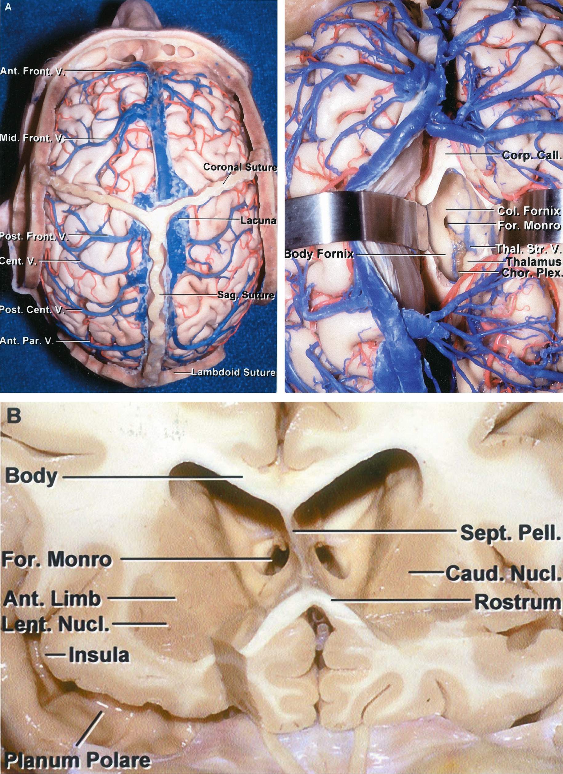
Figure 1: The coronal and sagittal sutures are shown in relation to the cerebral surface anatomy (top, left). The foramen of Monro is shown in relation to the cerebral surface anatomy (top, right). Compare the location of the coronal suture with that of the foramen of Monro. A coronal section shows the foramen of Monro (bottom). The catheter tip is angled toward the medial canthus to end at this foramen which is considered the ‘zero point’ of the intracranial compartment. The intracranial pressure is measured relative to this point (Images courtesy of AL Rhoton, Jr)
The trajectory of the catheter is toward a point ~ 1cm anterior to the tragus on the sagittal plane and toward the medial canthus on the coronal plane. As a rule of thumb, the drain should enter perpendicular to the skull to reach the foramen of Monro. These landmarks require that the foramen is located in the standard midline position and not distorted by the underlying pathology.
Patient Position
The patient is placed in the supine position with the head of the bed elevated approximately 30-45 degrees. The patient’s head is placed in a neutral anatomic position because any head rotation will lead to significant disorientation of the surgeon’s landmarks. Since this procedure is most often performed on a lethargic or sedated patient, the head should be held in place by an assistant to minimize movement during burr hole placement (craniostomy).
Procedure
After clipping the hair to expose Kocher’s point, the midline is clearly delineated based on the bridge of the nose and double-checked. Kocher’s point is marked and a 1-2cm linear incision is drawn through this point.

Figure 2: The standard Kocher’s point is identified (medial blue dot). I usually place the burrhole about 1cm lateral to the standard location of Kocher’s point to further avoid the parasagittal veins (lateral blue dot).

Figure 3: Kocher’s point is shown in relation to the coronal suture and midline. The tip of the catheter should be aimed at the foramen of Monro, the hypothetical ‘zero point’ of the intracranial space. The top inset shows the catheter entering perpendicular to the skull, an important principle in placement of the catheter. The bottom inset illustrates Kocher’s point located 1cm anterior to the coronal suture and 3cm lateral to the sagittal suture.
A local anesthetic is infiltrated into the scalp, not only along the incision, but also along the planned path of the trocar for subgaleal tunneling of the drain catheter later in the procedure. Once the incision is made and the small self-retaining retractor placed, the periosteum is dissected away from the calvarium.

Figure 4: The drill must enter the skull at a perpendicular angle and with the same trajectory as the EVD catheter (top image). This maneuver is essential since the drill’s small diameter bit, together with the thickness of the skull, will determine the allowable angles or trajectories through which the catheter can enter the brain. Any slight deflection of the catheter because of an inadequate craniostomy leads to serious alterations in the final trajectory of the catheter tip (lower image). Since this deflection occurs after the catheter has entered the brain, the operator will not be cognizant of it.
An inadequate craniostomy is defined as a small burr hole with irregular edges at the inner table of the calvarium, leading to deflection of the flexible EVD catheter tip. Therefore:
- a drill bit with a larger diameter should be used, and
- the bit should be retracted and advanced multiple times along the thickness of the skull to ensure that the inner edges of the craniostomy are adequately drilled and no bony ledge is present to deflect the catheter.

Figure 5: If the drill has not penetrated the dura, a blunt needle can be used to perform the durotomy. The drain is then passed in the planned trajectory (described above) with its stylet to a depth of 6 to 6.5cm as measured from the level of the scalp.
Any further advancement of the catheter beyond 7cm in order to obtain CSF should alarm the operator about the erroneous angle or location of the catheter tip into the temporal horn, interhemispheric fissure, third ventricles, Sylvian fissure, and even basal cisterns. Under these circumstances, the catheter should be removed, and often it needs to be angled slightly more medially and posteriorly.

Figure 6: View of the ventricles through the brain from the operator’s perspective. The trajectory of the drain is toward the medial canthus on the coronal plane and a point ~1 cm anterior to the tragus on the sagittal plane. The tip of the catheter should lie near the foramen of Monro.
A ‘pop’ can often be felt as the tip penetrates the ependyma; CSF flow is then confirmed. The stylet should be removed and the catheter advanced for another 1cm within the ventricle so the tip is at the foramen of Monro. The distal part of the drain is tunneled under the skin and secured. Care must be taken not to sew in the drain when closing this small incision.

Figure 7: The drain is carefully tunneled under the galea to decrease the risk of infection. A non-toothed forceps instrument is used to hold the drain in place while this is done to minimize the risk of dislodging the catheter or inadvertently pushing it deeper into the ventricle (top inset and bottom photo).

Figure 8: The drain is secured to the skin at multiple points to reduce the risk of pullout. I use skin staples to secure the catheter to the skin.
Occasionally, the lack of CSF return from the catheter upon its insertion is due to low intraventricular CSF pressure, and not an undesirable catheter tip location. The operator should not prematurely remove and reinsert the catheter. Instead, a 10cc syringe should be used to gently withdraw fluid from the catheter. This maneuver often confirms the appropriate location of the EVD drain.
If three consecutive passes of the catheter do not cannulate the ventricle, the procedure should be aborted and performed by a more experienced colleague or under stereotactic guidance. The risk of intracranial hemorrhage increases significantly after three consecutive attempts.
EVD Malpositioning
Here is an example of an EVD that has been routed inaccurately most likely due to a small craniostomy.

Figure 9: This EVD catheter may have been only slightly deflected by the inner edge of the small burrhole (left upper coronal CT scan). The catheter barely missed the lateral ventricle (right upper image). Since the ventricle was not cannulated, the operator advanced the catheter beyond the allowed length, placing the tip of the catheter too deep (lower row).
Postoperative Considerations
If I make multiple passages or suspect catheter malpositioning, I request a CT scan immediately after the procedure to confirm correct placement of the EVD and absence of a hematoma.
Special consideration must be given for patients with ruptured aneurysms. Opening the EVD to drain at 0 or 5cm H2O may potentially cause an aneurysmal rerupture due to rapid changes in transmural pressure across the wall of the aneurysm sac. Unsecured ruptured aneurysms must be drained at no lower than 10cm H2O.
Patients with huge posterior fossa masses causing significant mass effect and potential cerebellar transtentorial herniation may require CSF drainage due to obstructive hydrocephalus. These patients may suffer from life-threatening upward transtentorial herniation if there is no back pressure from the supratentorial ventricular system. Their ventricles should not be drained at lower than 15cm H2O.
Patients with CSF leakage at the level of the skull base or spine should not be drained aggressively as this maneuver will lead to worsening of their pneumocephalus and neurologic decline. Communication with the nasal passages may lead to spread of infection and ventriculitis in the face of a foreign body (EVD) catheter in the ventricle.
Long-term EVD usage (>2 weeks) leads to increased rates of infection and ventriculitis. Patients with an active CSF infection should not undergo EVD implantation if possible.
Pearls and Pitfalls
- If multiple passes of the catheter are made without success, aiming slightly medially and posteriorly can increase the chance of success. Another option is to secure the catheter and obtain a CT scan. The trajectory can be corrected based on the location of the last pass.
- If you believe the drain is in the ventricle, but do not observe CSF return, a 10mL syringe can be used as a manometer or to gently withdraw low pressure CSF from the ventricle.
Please login to post a comment.